"Rolling My Own" Windings

mclovin

100 W
Joined
Apr 4, 2009
Messages
184
Location
Seattle
Hi All,
Does anyone know where to look to get technical info on the ins-and-outs of windings? I understand magnetic flux density and all that but I'm looking for something that formulaic for, say, take a motor that is configured as "such and such" and if I wind it at , oh, 10T then I will need wire gauge X, with an R of x Ohms and the K value will be blah blah and so on.

-Cheers.
 
If you know the motor dimensions, cross section to be wound, winding and termination scheme, and magnet strength you can get pretty close with formulation. Of course I don't know if off my head :lol:

http://www.reliance.com/mtr/mtrthrmn.htm
http://books.google.com/books?id=TsXEHPofiAYC&lpg=PT979&ots=QNJJbcaib4&dq=motor%20winding%20combinations&pg=PP1
 
there is also the forums for DIY RC motors.

www.powercroco.de

this is a german to english google translation. most of the motors described use a concentrated winding (tightly wound directly on each tooth of the stator) which is easy to do by hand. but there is little practical difference to the drum wound (wound on a temporary "buck" or form and then inserted into the stator slots) distributed windings used by many commercial motors like the Crystalyte.

the forum also has a design tool that shows the practical winding patterns for different numbers of poles and slots.

math and simulations are great. work wonders. waste lots of time. the practical approach is to make a test winding of a couple of turns of single strand wire in the desired pattern. fire up the motor with a low voltage current limited supply and measure the RPM. use that to determine the KV. then figure out the number of turns you need for your desired KV. that math is much simpler.

once you know the number of turns you want to fill the slots as completetly as possible. you can do this by either using thick heavy gauge wire or multiple strands of thinner wire. big stuff is hard to bend and form around the sharp corners of the stator but potentially allows for a denser fill. it is also easier to damage or nick the wire insulation. multiple strands are easier to form. this becomes a personal choice. i like multiple strands and normally use either 17AWG or 16AWG wire. i usually do a test to see how many wires i can fit into the slot and divide by the number of turns. that tells me how many parallel strands to use.

for example on a crystalyte X5 i know i can comfortably fit 32 strands of 17AWG into each slot.

rick

PS. get yourself some really hard wood like hicory. like the stuff used to make hockey stick handles. don't need much. just need a couple of pieces you can shape into something that resembles a straight screwdriver blade. these are really usefull for pushing the windings down into the slots without damaging the insulation. also a few more that can be used to wedge the windings into the slots so the wires don't pop out of the slots as you manipulate the stator. you can probably get a broken stick for free at the local arena if you don't play hockey yourself.
 
Indeed, the math is possible, but it does take a lot of time to understand and I think it'd be more time-worthy of someone designing a motor for market. I think there are "motor simulators" out there but they're undoubtedly pretty expensive.
 
Once you have one value (by the method Rick suggested) then:

Doubling the number of winds halves the velocity constant and doubles the torque constant, etc.
 
yes just plain old multiply and divide after that. instead of all of the calulus required for calculating surfaces, volumes, density at distance etc. etc. and trying to measure all of that quickly.

it is said that Thomas A. Edison had a test that he gave candidates applying for engineering positions with him. he would give them a glass shell from a light bulb and ask them to find the exact volume. most would run off and start measuring dimensions, creating complex equations and spend a couple of days working on it. when they gave him an answer it was usually inaccurate. Edison would demonstrate by filling the shell full of water and them pouring the water into a measuring flask. you could then read the result directly in under a minute.

rick
 
Thanks! You guys rock...again.

Yeah, I prefer emperical data to theory and numbers any time but........theory and number crunching are free (no need for a lab or expensive equipment) which is good as I learn. It's pretty cheap to crank out a hundred spread sheets of data but ultimately I'll need to get my hands dirty and test. Hopefully I don't let to much smoke out as I roll my own. :D Sorry, I couldn't resist it.
 
Wire gauge and resistance do not effect Kv. Always use thickest wire possible for given/desired number of winds. Better for efficiency.

To determine number of winds for a desired Kv_new you start with a quick-and-dirty 10, 20, ... wind job. You can do this with (very) thin wire, no current flowing during Kv measurement. Determine Kv_old using the power-tool method. Now, since winds_new * Kv_new= winds_old * Kv_old = always constant

winds_new = winds_old * Kv_old / Kv_new (1)

winds_old = 10, 20, ...
Kv_old = from power-tool method
Kv_new = desired Kv


Motor_rewinding_101
http://www.gobrushless.com
-> knowledge base
-> basic overview (1-5)

Tips and tricks, checks and tests, may keep you from frying yer ESC and/our controller:
http://www.rcgroups.com/forums/showthread.php?t=240993

Vriendelijke groeten ;) Ron
• brushless motor building tips & tricks • diy brushless motor discussion group
• Drive Calculator download & discussion group • int. electric fly-in, Nijmegen, the Netherlands
 
Hi ron van sommeren,
Thanks! That's very useful info.

From what I've read here it sounds like the easiest way to get some numbers is to first start with a motor, get Kv them I'm off and running with my spreadsheets and such. Looks like I will need to spend some money up front. Oh well. Educations are rarely free. :)
 
ron van sommeren said:
Wire-gauge and -resistance do not effect Kv. Always use thickest wire possible for given/desired number of winds. Better for efficiency...
Apart from efficiency considerations, thin wire also leads to a higher drop in rpm when motor is under load.
The motor will be less 'stiff'.

Vriendelijke groeten ;) Ron
• brushless motor building tips & tricks • diy brushless motor discussion group
• Drive Calculator download & discussion group • int. electric fly-in, Nijmegen, the Netherlands
 
ron van sommeren said:
... Apart from efficiency considerations ...
Higher efficiency does not only mean that the motor makes better use of the batteries' power, it also means the motor is able to handle a higher power input before hitting its maximum temperature mark i.e. a the power/weight ratio will be higher.

An example:
Say the motor has an efficiency of 70% and it can handle 500Watt input. That means it can get rid off 30%*500=150Watt excess heat. Now, by cramming in thicker wire (and/or using better stator-iron, segmented magnets), efficiency increases to say 75% (I'm a bit optimistic here). The motor's ability to loose those 150Watts has not changed (by radiation, convection and conduction). This means the motor now can handle 600Watt before it hits the 150Watt (25%*600Watt) losses mark. An efficiency increase of 5% gives an increase in the power to weight ratio of 20% (from 500Watt to 600Watt). That's why efficiency plays such an important role, in any motor design: efficiency governs maximum power. The motors weight may have increased a bit due to more copper.

If you increase efficiency of a 80% efficient motor to 90%, specific power would increase by factor 2, i.e. 100%more.

Vriendelijke groeten ;) Ron
• brushless motor building tips & tricks • diy brushless motor discussion group
• Drive Calculator download & discussion group • int. electric fly-in, Nijmegen, the Netherlands
 
ron van sommeren,
Just to clarify....I'm assuming that when you say that a motor hits a heat "limit" that beyond that limit the motor will fail?
 
ron,

i understand what LRK windings are and what distributed whindings are. but i am confused at to what "DLRK" windings are.

rick
 
D-LRK stands for 'distributed LRK'. Coils on all statorpoles instead of on half the statorpoles. You have to be careful though when specifying number of winds: N winds on half the poles (LRK) gives about the same motor as N/2 winds on all poles (dLRK). Hardly any difference between LRK and dLRK. And there's also adLRK, a-symmetric LRK :)

An excellent dLRK winding tutorial
http://www.rcgroups.com/forums/showthread.php?t=736580

Classic LRK winding tutorials
pictures:
http://www.rcgroups.com/forums/showthread.php?t=523039
bible, with the original LRK articles (in English) published in the German ElektroModell Magazine in 2000 and 2001)
http://www.torcman.de/peterslrk/index_eng.html
Building/winding manual:
http://www.torcman.de/motoren/manuals/anl_eco_200e_scr.pdf

If you haven't done so yet, I suggest first reading Brian Mulder's excellent motorbuilding articles, they cover the all the basics and you'll find a table with winding diagrams in it:
http://www.southernsoaringclub.org.za/
-> Articles by SouthEasterners.
-> Electric Motors - part 1-5

Then have a look at my first post in the 'cd-rom tricks' sticky thread, several tips about preventing shorts and keeping your controller from getting toast, #15 to #27:
http://www.rcgroups.com/forums/showthread.php?t=240993

And of course http://www.powercroco.de (use http://babelfish.altavista.com for translation)
 
ron van sommeren said:
... To determine number of winds for a desired Kv_new you start with a quick-and-dirty 10, 20, ... wind job. You can do this with (very) thin wire, no current flowing during Kv measurement. Determine Kv_old using the power-tool method. Now, since winds_new * Kv_new= winds_old * Kv_old = always constant

winds_new = winds_old * Kv_old / Kv_new (1)

winds_old = 10, 20, ...
Kv_old = from power-tool method
Kv_new = desired Kv ...
Manuel V's wind/turn calculator
http://www.rcgroups.com/forums/showthread.php?t=1062406

Vriendelijke groeten ;) Ron
• brushless motor building tips & tricks • diy brushless motor discussion group
• Drive Calculator download & discussion group • int. electric fly-in, Nijmegen, the Netherlands
 
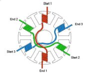
With LRK terminated wye i want to put the wye bundle on the other side from the phase wires and therefore half a turn on half the wound teeth. would this be magnetically balanced or should I also do half a turn on the other tooth per phase as well and end up with the transits also on the other side from the phase wires?
*** after hearing this would be fine and testing it shows fine with half turns and the wye on the other side from phases. I don’t have the tools to see any detrimental effects***
 

Attachments

  • 4347AD32-8F69-4E1B-A2E9-818D1033D9A3.jpeg
    4347AD32-8F69-4E1B-A2E9-818D1033D9A3.jpeg
    43.8 KB · Views: 507
Back
Top