
You are using an out of date browser. It may not display this or other websites correctly.
You should upgrade or use an alternative browser.
You should upgrade or use an alternative browser.
Has anybody rewound their HXT/Turnigy motor?
- Thread starter swbluto
- Start date
Jeremy Harris
100 MW
I've rewound one of my Towerpro 5330 motors three or four times now, whilst experimenting to get a low Kv for my electric boat project. I started off with multi-strand polyurethane enamelled copper wire, the same stuff that the motor was originally wound with. This was made up by buying a reel of wire from a electronics stockist here in the UK, RS Components, then making up the multi-core by stretching several lengths down the length of my garden and winding the lot on to a drum ready for winding.
The original winding on my motor was ten turns made up of 14 strands of 28g wire. I found that I couldn't get more than eleven turns on the motor using this wire configuration and even then it was very hard to wind neatly. I tried fewer strands of 26g and 24g wire, before finally settling on twelve turns of single 18g wire. As I'm not running this motor at more than about 400 watts this seems fine and gives me a Kv (in wye) of 98.
I think I've got pretty close to the maximum amount of copper I can with the 18g wire. It was hard work to wind, but has come out more neatly than the multi-strand wind and seems to have a lower resistance (which is good for efficiency). I think these motors are only wound with multi-strand at the factory because it's easier, not because it's better. Some have argued that multi-strand wire has lower losses because of skin effect, but when I did the sums for the frequencies that our controllers PWM at this proved not to be the case - the losses from skin effect are negligible up to a few tens of kHz.
Winding a bigger motor would be easier, as the biggest problem I encountered was getting the wire to lay flat in the slots. Once you have a few turns wound you need a thin, flexible but tough tool to get down in the slots and flatten the wire down. You also need to keep quite a lot of tension on it to ensure that it bends neatly around the ends - wearing tough gloves is kinder on the hands.
Hope this helps.
Jeremy
Thanks Jeremy for the insight. I was looking at your motor and noticed that it seemed structurally similar to the motor I'm trying to rewind. Did you remove the "front" off the motor in order to rewind the stator? It appears the "front" is glued onto the stator on my motor using some kind of black glue or epoxy. While there seems to be a little space to squeeze wires in, it seems like it'd so much easier if the front was removed and I'm sure the stator was wound at the "factory" without the front there and it was glued on after it was wound.
Jeremy Harris
100 MW
Sorry, I should have added this. Yes, I did remove the stator from the alloy part.
As my motor was already scrap (I'd accidentally damaged the wiring when milling slots for the Hall sensors!) I just removed the bearings and heated the stator up with a hot air gun. This softened the glue that was bonding the iron stator to the alloy bearing housing and front mount.
I was able to separate the two fairly easily by holding the stator in a vice (gripped between two bits of shaped softwood as jaws to protect it) and twisting the front plate until the glue bond gave way. It was then just a matter of pushing the bearing housing part out.
The secret here is to use a fair bit of heat from the hot air gun, but not enough to damage the insulation painted into the stator slots. The glue bonding the stator to the alloy part seems to be epoxy, which softens at temperatures around 150 deg C or so. Once softened, it seemed to go sort of powdery as it broke up under force and the joint came away quite cleanly with a bit of twisting and pulling.
I reassembled it after I rewound it finally with ordinary epoxy glue. I found that I could test the motor without gluing the stator on, it would hold with just a push fit for low-load testing for Kv, Io etc. This made it easier to play around with different winds, as all I needed to do was pull the stator back off, strip the wire off and wind it again.
Jeremy
liveforphysics
100 TW
Jeremy- You are so awesome. If you don't mind, it would be great for everyone here to get to see some pics of the disassembly and winding process. Even in RC, people rarely seem to wind there own motors these days, and very rarely do you see motors in E-bike sizes being wound.
Jeremy Harris
100 MW
Thanks for the kind words Luke. Unfortunately, I didn't bother to take any pictures of the motor when I had it apart and it's not glued back together again in my electric boat pod.
I found a fair bit of information on motor winding from some really good links that Ron Sommeren posted on one of the RC groups, although I forgot to bookmark the post. I'm sure a search on one or other of the RC forums would find his list of links on motor winding, it's really very good indeed for basic stuff, like how to do the wind.
I did take care to do a sketch showing exactly how my motor was originally wound before I took it apart. I also took careful note of where the wires came out from each coil, the number of strands of wire used etc. The motor was wound as Distributed LRK (often abbreviated to dLRK), which seems to be the most common method for a 12 slot stator.
I searched high and low for a way to work out how many turns I could get on the motor at any particular gauge of wire, including resorting to drawing a slot up in CAD and modelling it. What I found was that it was difficult to predict with accuracy, as it's very hard to keep windings absolutely neat, especially if they are wound as they are originally, with multi-strand wire. I think I would my motor three or perhaps four times in total, until I got a good feel for the best compromise between low winding resistance (for high efficiency) and high number of turns (for low Kv). My aim was to directly drive a boat prop of 12" in diameter at a maximum rpm of around 800 at the highest possible efficiency from a 63mm diameter motor though, so a very different set of requirements from those needed to drive a bike.
Knowing what I know now, and applying it to a bike motor, I'd suggest going for the fastest motor speed that you think you can live with, probably set by the practical reduction ratio you can accommodate without too great a power loss. Spinning motors faster gives more power for little or no increase in heating loss in the windings. The downside of this approach is noise and complexity, plus an increase in mechanical loses, things I didn't want in the boat unit, but which might well be acceptable on a bike.
Jeremy
Jeremy Harris said:Knowing what I know now, and applying it to a bike motor, I'd suggest going for the fastest motor speed that you think you can live with, probably set by the practical reduction ratio you can accommodate without too great a power loss. Spinning motors faster gives more power for little or no increase in heating loss in the windings. The downside of this approach is noise and complexity, plus an increase in mechanical loses, things I didn't want in the boat unit, but which might well be acceptable on a bike.
Jeremy
I'm finding that the practical gearing ratio is quite low since I'm using a belt, my wheel's timing pulley is 60 teeth, and 15 teeth on the timing seems to produce shredded belts somewhere around a pitiful 1.5 kW at startup. I'm hoping that I can pull more power through the system by increasing the timing pulley size (To somewhere around 20-25), but this increase in size made the existing high-kV motor a little less efficient and draw more motor current, which put the ESC in more danger since the ESC's heat is largely attributable to motor current. With a lower kV and higher resistance, the motor current should be reduced which should help prevent the ESC from frying.
Also, yes, I'm rewinding mine because I also damaged the wire by "servicing" the motor (I was just taking it apart). But since I'm rewinding it, I'm thinking "Hey, why not! Let's make this the *perfect* RC motor".
Just as a side question, does anyone know if the original 80-100 130kV HXT motor was terminated by star or delta? I'm trying to decide how many turns I should do to get my desired kV ratios based on how many turns the previous motor had (Which was 8 turns). I'm hoping to have it switchable from star and delta on the fly so I can the best motor profile when I need it. From my simulations, it seems the lower kV option should have better low-end torque/acceleration AND lower motor current which means reducing the chance of popping the ESC (The lower kV would also be tuned to be "neighborhood friendly"), while the higher kV option would allow me to max the speed of the vehicle to the battery's power limits for those occasions where doing so would be beneficial (i.e. a short jaunt along a 30-35 mph road because I have no other options).
Jeremy Harris
100 MW
Just as a side question, does anyone know if the original 80-100 130kV HXT motor was terminated by star or delta?
I'm near-100% certain that it would have been wired delta, as I've not yet seen one of these outrunners that's been wired wye as standard. It's easy to tell, as if it's wired wye you will be able to see the centre connection of the three windings. The motors I've converted from delta to wye have all ended up with the centre connection poking part-way through one of the vent holes in the face, as there's little room for the joint to go anywhere else.
If you used the same wind as the motor was wound with originally, but switched it from delta to wye, then that would give a useful decrease in Kv on it's own (the 130Kv motor would come down to around 72Kv). My experience has been that the delta/wye conversion on these motors tends to reduce the Kv by a factor of about 1.8, rather than the theoretical figure of about 1.73 that's often quoted, but there is often a fair bit of error in the quoted Kv anyway. My 215Kv motor was really about 230Kv and the 170Kv one was really about 180Kv.
Jeremy
Jonathan in Hiram
1 kW
- Joined
- Oct 6, 2009
- Messages
- 446
Jeremy Harris said:My experience has been that the delta/wye conversion on these motors tends to reduce the Kv by a factor of about 1.8, rather than the theoretical figure of about 1.73 that's often quoted, but there is often a fair bit of error in the quoted Kv anyway. My 215Kv motor was really about 230Kv and the 170Kv one was really about 180Kv.
Jeremy
I read somewhere the other day that the difference between the 1.73 factor and the 1.8 factor you mention is due to the shape of the wave our controllers use to drive our brushless motors, a sinusoidal wave gives a 1.73:1 and the more angular wave of our controllers makes it closer to 1.8.
I looked for the link but can't find it now.
Thud
1 MW
I just striped a turnigy 5065-380kv. I sawed through a phase wire with the can after tying the wires back to tightly to the frame on my bike. Totaly my fault. The advertised Japanees bearings say made in thialand. (?)
I boiled the stator & bearing tube in water for 10 min to soften the epoxy.
EDIT I just found the answer to my question above
  )this little motor was wound as a distributed LRK.
Not what I would expect on a super cheap motor.
Jeremy, when you re-wound did you stay with the dLRK?
I boiled the stator & bearing tube in water for 10 min to soften the epoxy.
EDIT
I just found the answer to my question above Not what I would expect on a super cheap motor.
Jeremy, when you re-wound did you stay with the dLRK?
Jonathan in Hiram said:Jeremy Harris said:My experience has been that the delta/wye conversion on these motors tends to reduce the Kv by a factor of about 1.8, rather than the theoretical figure of about 1.73 that's often quoted, but there is often a fair bit of error in the quoted Kv anyway. My 215Kv motor was really about 230Kv and the 170Kv one was really about 180Kv.
Jeremy
I read somewhere the other day that the difference between the 1.73 factor and the 1.8 factor you mention is due to the shape of the wave our controllers use to drive our brushless motors, a sinusoidal wave gives a 1.73:1 and the more angular wave of our controllers makes it closer to 1.8.
I looked for the link but can't find it now.
The ESCs used to drive brushless motors do output a sinusoidal wave at full throttle (That is, when the duty cycle is 100% - there's no "off time" for the mosfets). I don't know about other controllers, but that's what the Phoenix HV does and I'd assume others would too.
Jonathan in Hiram
1 kW
- Joined
- Oct 6, 2009
- Messages
- 446
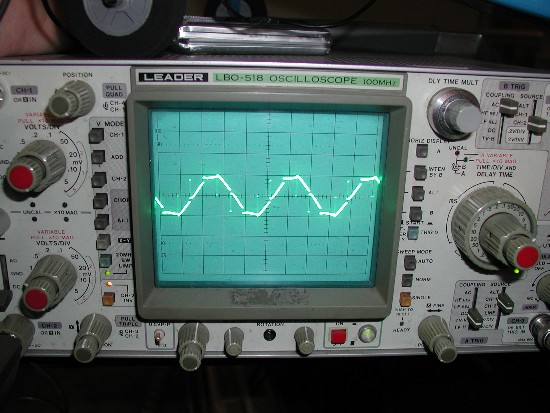
swbluto said:The ESCs used to drive brushless motors do output a sinusoidal wave at full throttle (That is, when the duty cycle is 100% - there's no "off time" for the mosfets). I don't know about other controllers, but that's what the Phoenix HV does and I'd assume others would too.
Here is an oscilloscope picture of the wave shape of a Phoenix 35 driving a Mega brushless motor at full throttle.
The thread showing the pictures is here:
http://www.rcgroups.com/forums/showthread.php?postid=1920716#post1920716
Here's my video showing the Phoenix HV 85 driving a 63-74 turnigy outrunner.
http://www.youtube.com/watch?v=OzenQU_lcBY
I was measuring the battery current right before the capacitor leads into the controller which isn't *directly* the phase current (The capacitors also provide some of the current which may have changed the waveform shape in some other way). Are you sure that's the phase current and not the gate drive signal? The motor provides a sinusoidal BEMF due to the instantaneous magnet position which would impart at least some sinusoidal artifact on the phase current.
edit: I think the capacitances involved may have "rounded" the edges of the trapezoid to make it appear sinusoidal on my oscilloscope. I'll have to measure the phase currents directly, next time.
Jonathan in Hiram
1 kW
- Joined
- Oct 6, 2009
- Messages
- 446
The *current* is closer to sinusoidal due to inductance effects "rounding off" the corners of the angles. That picture was of the voltage across two motor leads.
Here is the quote from the original poster.
Here is the quote from the original poster.
Here I connected voltage probes to two motor wires. Since this is a delta wind motor that means the probes are connected across the two terminals of one of the three phase windings.
Jeremy Harris
100 MW
My TowerPro motor was originally wound dLRK and I rewound it the same way. I did play about with the idea of bringing all twelve windings out separately, so that I could switch winding configurations to see what worked best, but there wasn't really enough room between the front alloy case and the stator to feed the wires out neatly. It was also going to mean more winding resistance, as the winding "tails" would have been much longer.
AFAIK, dLRK is pretty much optimum for a 12 slot motor, so I'll leave it as is now.
Jeremy
AFAIK, dLRK is pretty much optimum for a 12 slot motor, so I'll leave it as is now.
Jeremy
Hey, I was wondering, how do people remove the windings from these motors? Parts of the wire seemed to be glued in and so I took to it using a wire snipper and yanked out what I could, but this seemed to be slightly inefficient and it ended up gouging parts of the stator's insulation. Does anybody know of a better way?
liveforphysics
100 TW
swbluto said:Hey, I was wondering, how do people remove the windings from these motors? Parts of the wire seemed to be glued in and so I took to it using a wire snipper and yanked out what I could, but this seemed to be slightly inefficient and it ended up gouging parts of the stator's insulation. Does anybody know of a better way?
Cut-off wheel ran along the end of all the windings on the bottom side, then poke and push to break the varnish loose that retains them in the slots, and slide the whole mess out the top.
liveforphysics said:swbluto said:Hey, I was wondering, how do people remove the windings from these motors? Parts of the wire seemed to be glued in and so I took to it using a wire snipper and yanked out what I could, but this seemed to be slightly inefficient and it ended up gouging parts of the stator's insulation. Does anybody know of a better way?
Cut-off wheel ran along the end of all the windings on the bottom side, then poke and push to break the varnish loose that retains them in the slots, and slide the whole mess out the top.
Was this before or after you removed the "front" of the stator? (It's glued to part of the stator that has the windings)
I'm asking because it doesn't seem like it wants to do anything after I cut the windings along the "bottom" using a cutoff wheel. I made one cut/slot per pole.
liveforphysics
100 TW
If you cut through all the end-turns of the windings on the bottom, so the bottom of the stator is a flat flush surface, you can poke a screw driver in that gap between the end plate and stator, and pry up on the winding sections to break them all loose, then slide them all out the top.
If your motor has something unique about it that makes this impossible, then you might need to find a new technique, or just dip it all in a solvent to disolve the glues and un-wrap it.
If your motor has something unique about it that makes this impossible, then you might need to find a new technique, or just dip it all in a solvent to disolve the glues and un-wrap it.
The windings seem very stiff, so it seemed like they were impossible to remove.
On closer inspection, however, I see two different "layers".Around a given pole, through the cut-off bottom part of the winding, it seems like there's a bright copper colored layer on the inside of a winding and then a dull white layer on the outside, even though it's still windings. The copper colored stuff is fairly flexible whereas the dull white external layer seems "stuck" as if it's been impregnated with some kind of glue and it's very hard to remove (Compared to the HXT 6 kW motor I had). Is this what you had on your motor? This layer is like 5-6 windings thick and it seems problematic.
So, assuming it's some kind of glue, what kind of solvent would be recommended? I have acetone but I'm not sure if that works on glues.
btw, this is a motor that I had over-heated, but it appears only one pole has the bad windings (Black burnt stuff.).
Well, this sucks. It seems that in the process of trying to remove the front of the motor from the bearing tube by
1) Securing it in a vice
2) Getting the part really hot using a heat gun
3) Trying to get it off by banging the hell out of the front with a mini-sledge hammer
It appears some of the slices of the stator started to come apart. So, I think it's basically "ruined" at this point. My original plan was to remove the stator, try to cut off the windings at the front and then pry away the windings from the stator now that the front and bottom would've been cut off.
Actually, it's probably not quite "ruined"(Just bound the stator back together and work within limitations?), but it seems to be at a point where I'm really frustrated by this piece of unmaintainable crap.
So, now I'm looking for a different motor. One that is, above all, maintainable. So, a looking I'll go.
False alert! I got a special tool that was used to remove my scooter's brakes and used that to twist the motor's front. Surprising thing was... though, is that I ended up using it on the motor when the motor had cooled off to 150 degrees Fahrenheit and it started turning. I was like... what??? Epoxy doesn't break loose at the temperature! Eventually it stopped turning, so I turned it the other way and the bearing tube / front started coming out.  I took it apart and apparently it seems that the front just simply screws into the motor. Amazing. It looks like it might actually be partially designed to be maintainable (Or possibly just easy to assemble).
So, I'm going to attempt to remove the windings and repair the damaged parts of the stator and try to rewind it. I hope I get lucky.
EDIT:
So, in the process of trying to remove the windings, I eventually realized that the sticky stuff/glue that impregnated the outer layer of the windings was really making removal impossible. So, now I'm soaking the thing in acetone and hoping that it comes off or something. I'm not sure how long it should soak but I think 3 hours should be good enough? Well, I'll find out in 3 hours.
So, I left the stator in acetone for about an hour before checking it. No cigar. So overnight I said. So, it stayed overnight and in the morning, I picked it up and the glue still didn't come apart. However, the stator's insulation did.
So, if I eventually take off the windings, it appears I'll have to strip the insulation and recoat the stator. No big deal, methinks. It appears that covering the outside of the stator and the middle with a cylinder and maybe some tape would insure that the paint would get where it needs to go.
However, I still need to get the windings off. Can anyone recommend another solvent to try?
Also, does anyone know if it's possible to order a replacement stator? Or maybe some equivalent from somewhere?
olaf-lampe
10 kW
During my 'professional' motor winding days, I used to wind the wire around a simple plastic tube. The tube has a hole where I stick the wire through it and bend the wire sharp on the inside of the tube, so it can't get loose. That way you can use much more force and still have sensitivity not wearing gloves.
I always got my wire from a local rewinder-pro. They always have some leftovers for sell.
In my archives on the other PC I have an excel sheet that helps to calculate the max wire diameter for a given stator and number of turns.
I'll post it here tomorrow. ( hope it's not copyrighted. I found it on the net somewhere )
One of my favoured pages these days ( beside Ron van Sommerens yahoo group ) was:
http://www.powercroco.de/index.html
Since your stator already needs new insulation, you can put the whole thing in an oven and see what comes apart first.
!Smoke!
Don't use Mrs. swblutos oven for that
Olaf
Attachments
So I put it in an oven and smoked the whole thing at 450 degrees fahrenheit. I took it and it doesn't seem any uneasier to wind. Oh my lord, what did they do to it? Was it wound so tightly that the insulation just congealed with other wire's insulation and made an indestructible molecular bond?
The 80-100 I had was far easier to unwind than this has been.
Edit: Wait a minute. It seems some strands are actually coming out this time! This seems encouraging. I'll continue onwards now that I'm armed with tweezers.
The 80-100 I had was far easier to unwind than this has been.
Edit: Wait a minute. It seems some strands are actually coming out this time! This seems encouraging. I'll continue onwards now that I'm armed with tweezers.
Similar threads
- Replies
- 3
- Views
- 110
- Replies
- 5
- Views
- 236
- Question
- Replies
- 3
- Views
- 98
- Replies
- 5
- Views
- 108
- Replies
- 1
- Views
- 88