Kepler eboost. The journey and evolution

Kepler

10 MW
Joined
Nov 8, 2009
Messages
3,922
Location
Eastern suburbs Melbourne Australia
I am sure a few people are getting sick of friction drives but love them or hate them, they are here to stay.

Adrian's Commuter Boost has been the focal point for quite some time now and as the active thread, I have been hopefully contributing to the forum via this discussion. However, with Adrian now looking at seriously selling some kits, I felt it was more appropriate for me to start up my own thread again rather then possibly stepping on toes.

To be clear, this is not about me trying to sell my own kits via the forum at this point. My drive is currently not available for sale and wont be for a few months yet. The purpose of this post is to just show the direction I am taking and where my development is currently up to.

For those who may be interested, I ended up manufacturing 40 of the original kits. These sold quite quickly and was an invaluable exercise in teaching just exactly what was involved in being a manufacturer. Financially, the exercise did me no favours. I think I broke even or maybe a little in front so no complains but certainly no windfall either.

The exercise taught me how important it was to optimize the design and to reduce both parts count and manufacturing cost. The original drive was costing me are around $250 to manufacture not including any of my time. Basically as it stood, it simply just wasn't economically viable. However, the concept and general design were sound and as such I felt it was well worth perusing.

Getting the opportunity to apear on the New Inventors television show was a fantastic experience. Winning the peoples choice award was a great honor and really lit a fire in my belly giving me the desire to take this to the next level. There is nothing like the exposure this sort of show gives you. I still get around 5 emails a day from the general public with enquires on where to purchase the drive.

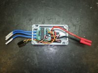
Most forum members understand the short falls of RC based systems and know what is required to ride around them. Unfortunately Joe Public doesn't. Subsequently much of my focus has been in making the drive idiot proof. The Mythical Kepler interface is the key to success with the general public and has been where most of my time, money and effort has been spent. I have a fantastic association with a US based software engineer who has put in countless hours in development time on this unit. Unfortunately however, we are all doing this part time so progress been slower then we all would have liked.

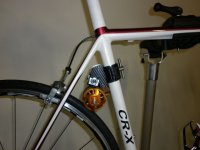
Interestingly, it has been much more difficult to make the drive low powered then high powered especially on 6S configurations. The silly Australian limit of 200W is particularly difficult to deal with however we have got this under control now providing smooth reliable control. Our software has 3 programable power settings. 200W, 750W, and 1200W. Other programable items are max speed, wheel diameter, km or mph, battery type, and battery voltage. It also interfaces to LCD screen that can display anything we decide on.

The throttle is a push button arrangement only as apposed to a twist or thumb throttle. A minimum start speed is programmed into the unit. This is set at about walking pace. The drive is designed to speed match so whenever assistance is required, pushing the throttle button will give just enough throttle to hold speed if the bike was on flat ground. Pushing the button in quick succession increases speed. releasing the button for more the 1/2 a second switches the drive off. Progressive electronic ramps have also been utilised to ensure smooth engagement and disengagement.

A key speed controller protection feature is that output power is mapped against wheel speed. Lower speeds have lower Watt settings and as such puts much lower stresses on the ESC under these critical loads.

So now to the drive itself.
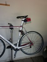
The design has gone through a number phases in a effort to reduce manufacturing costs and to improve the overall design. One of the major issues has been trying to make the drive fit as many bikes as possible. Other issues are the packaging of the electronics and battery configurations. I soon came to the realisation that the drive was never going to fit all bikes. However, I wanted to stay true to the original concept as much as I could especially keeping the quick release feature.

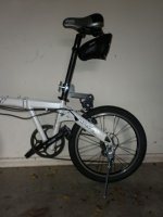
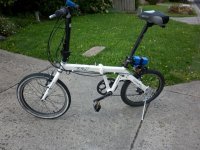
Enter the Mk 3 eboost Power Assist

This drive is designed around a modular set of parts whereby the major components are all common. However, a simple and cheap side frame replacement changes the configuration completely. The side frame replacement changes the drive from rear mount to centre mount and as such opens up a much wider range of bikes the drive can be fitted to.

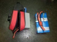
In addition to this, the rear mount can be use as a platform to carry up to a single 5800mah 6S pack. In this configuration, the entire drive system can be removed from the bike in seconds.

So thats where I am up to at this stage. Getting some interfaces out there is the next big push.
 

Attachments

  • P1000525.jpg
    P1000525.jpg
    35 KB · Views: 14,286
  • P1000488.jpg
    P1000488.jpg
    36.9 KB · Views: 14,286
  • P1000541.jpg
    P1000541.jpg
    77.9 KB · Views: 14,286
Great to see strong progress being made!

Wow, is it really cheaper to produce these units using Carbon fibre rather than Aluminium plating?

Any ballpark on time until availability , as well as price?
I hadn't till now considered friction drives amongst my e-bike desires, but the stealth and ability to bring the drive with me when locking up in a public area is becoming increasingly attractive to me. Too many dodgy looking tradies with envious eyes have been staring down my current bike as they walk past the bikeracks at uni (It's a construction zone everywhere at the moment). Knowing they often carry cordless angle grinders is a recipe for tears if I keep leaving such a spaceship looking e-bike locked-up, but unattended.

Will you make the drive available to ES members without the custom software controlled MCU for a lower price? I could handle the nuances of manual high-load/low-speed control, but I'd really prefer a linear throttle and I realise a linear voltage is likely incompatible with digital I/O signals feeding the Microchip as a digital interrupt. Or instead, could an ADC function - if the Microchip has it- be enabled to allow linear throttle control?
 
Well Kepler you have definitely made me appreciate the friction drive ALOT more! The above pics of the CF drives are puuure sex my friend. Not everyone's cup of tea we know but IMHO you have set the bar for ALL friction drives, best of luck with continued sales.

KiM
 
Very kewl! I am anxiously awaiting the interface! I have a 700C that is feeling unloved at the moment, and would be my first choice for short range (anything 20 miles or less) trips doing simple errands! :D
 
What kind of max range and speed are you seeing with a 6s 5800mah pack? That is amazing just how compact it is! for on road use, this is an AWESOME option!
 
Thanks for the replies. The actual finish is an adhesive vinyl carbon fibre look alike over aluminium :) I really wanted to see how the drive would look in a carbon fibre finish and this was a quick and easy way of achieving this. Production units will be black or blue anodised aluminium.
That being said, carbon fibre is not out of the question. Also considering light gauge Chro-moly as a possible material choice. This stuff laser cuts beautifully and in light gauge, is similar in weight to the aluminium plates.

In regards to the timing on release, I am still a around 3 months away. Of cause the drive will be available to ES members. :) Will offer it basically in any format requested. Price still needs to be set but improved production methods and hopefully a bit of volume will keep the price competitive.

In regards to linear throttle control, sure the chip can do it but we have made a business decision to concentrate on the button throttle only. The button throttle is very intuitive and in my opinion, suits friction drives down to a tee. Although I have never tested it, I think it would actually work quite well on a direct drive RC setup too. Something to try in the future :)
 
Whiplash said:
What kind of max range and speed are you seeing with a 6s 5800mah pack? That is amazing just how compact it is! for on road use, this is an AWESOME option!

Speed wise, 45 kph no problems. (scary on a folder but a great laugh when overtaking a lycra)

Distance wise. Easy 20km when used as a hill assist only. Around 10km really pushing. As it only takes 20 second to change a battery and the fact that the interface does a great job of monitoring battery condition, carrying a second battery in a backpack for extended range is an easy option.
 
Thanks mate.

Dampening is all software driven now. The motor has a progressesive ramp up rate that basically reduces torque as it approaches the end stops. Sound simple but it took quite a bit of develoment to get this right. Result is silky smooth engagment and disengagment without need for mechanical dampening. This then gave me the oportunity firstly to reduce the parts count and to make the drive more modular in its construction.
 
Did some work on packaging up the mid mount configuration. I found a nice seat bag that fitted 2 x 5S 5000mah and also has a flat bottom with a hard plastic insert. I wanted to hide the main battery wires inside the bag also and just have the phase wires and controls plugs exiting. Its hard to find the perfect off the shelf box. The box I have used has internal threaded stand offs for mounting boards. I have used these to mount the box to the board. The ESC and interface are mounted to the lid of the box so they all come away for easy access. The box is a little generous in size for the package but it does make it easier get all the components in. The interface is an older style unit. The new interface board is a tiny 36mm x 44mm to match the with of the ESC.

I wish I could mount the ESC and interface as part of the drive package but this just doesn't work for the mid mount.
 

Attachments

  • P1000564.jpg
    P1000564.jpg
    47.8 KB · Views: 14,061
  • P1000567.jpg
    P1000567.jpg
    53.1 KB · Views: 14,061
  • P1000570.jpg
    P1000570.jpg
    36.6 KB · Views: 14,046
These look simply amazing, it's obvious how much time you've put into their design. Keep up the good engineering.
 
One of the things that I have never been 100% happy with the direct out-runner drive concept has been the need to be very accurate with the tire to motor clearance to ensure consistant pickup. Basically the current design requires the tire to lightly brush the motor when coasting. This has worked quite well however this very light contact makes a constant scrapping sound. Also the flex in some seat posts makes the setup even more critical.

I have experimented with a few different concepts to mechanically drive the motor towards the tire in the past but was never really happy with the results. Even tried using an RC servo to give the motor the initial push. This actually worked quite well but made the drive over complicated and as such was shelved. It makes much more sense to use the rotating action of the motor to move the swing arm rather then adding secondary systems and in the past I have tried a cam arrangement mounted on the 10mm motor shaft to push the swing arm back. This idea caused more problems then it solved and as such was also shelved.

Inspired by "rearengine's" lateral thinking on his drive, I thought I would revisit the swing arm launch concept and see if I could come up with a simple but effective method of achieving a similar result. My first thoughts were to simply have a launch ramp just above the motor however I quickly realised this would drive the swing arm assembly in the wrong direction. This meant that the launch ramp would need to be under the motor for it drive the motor towards the tire. Not particularly feasible for this drive design as it would be very bulky and not particularly elegant.

Recent design changes to a single swing arm arrangement have freed up the 10mm motor shaft on the the opposite side and as such gave me the opportunity to use this shaft to somehow drive the swing arm assembly back. Subsequently I came up with the following design to drive the swing arm back towards the tire.

View attachment 2

The shaft has a piece of 3/8th heavy duty fuel tube over it. This was nice press fit however a locking collar was still required to stop the rubber tube naturally wanting to screw off.

P1000574.jpg

The picture below shows the swing arm assembly in the drive position. The actual amount of surface area required to drive the swing arm back only needs to be very small. This setup moves the drive about 3mm giving me plenty of motor to tire clearance when coasting.


So far, preliminary testing has been very positive. The extra parts count is very small with the assembly easy to remove if required without stopping the drive working as per the original design. Now to get some serious km's on it and see how well it stands up to every dat use.
[youtube]tgZVWDXdBiM[/youtube]
 
I travel around a bit with work, to the same bases. I often leave a bike at each base. One of these kits would be great. Could carry with me in aircraft hold baggage, and stick on each bike when I get to where I am going.
How much are they likely to be? or what other 'ready to go' designs like that are available now from other people ...I want one

Neil
 
Kepler !! Vary vary nice indeed... great :idea: The heavy snapping noise I suppose is the preasure it needs to get traction coming out of the gate, or is it to hold it off when coasting ?
Very interesting I'll be watching for sure ... Bill
 
Thanks rearengine. The snapping noise is due to having quite a bit of tension on the roller. This is adjustable and I have found that the tension need only be very light to get the motor to move off the ramp under actual riding conditions.
 
NeilP said:
I travel around a bit with work, to the same bases. I often leave a bike at each base. One of these kits would be great. Could carry with me in aircraft hold baggage, and stick on each bike when I get to where I am going.
How much are they likely to be? or what other 'ready to go' designs like that are available now from other people ...I want one

Neil

Still working on final pricing as the design is still evolving. I am now close though both mechanically and electronically. Mid year is my target to have a product ready for sale again.
 
Another solution (if you need this ramp) that would work on your mid mount is to attach the ramp to the seat tube, have it made from steel with a rubber skin, and use the motor flux leakage to magnetically attract to the ramp.

Just an idea. :)
 
Kepler (and rearengine),
The ramp is a very elegant solution. The video makes it very clear how 'launch' is achieved. What is not as clear (to me at least) is how 'park' is achieved. From the video it appears a nudge is needed to return the motor when off to its original parked spot. Does it return to the park position by gravity, spring or other method?
 
Hi Kevo. The park is achieved via a spring mechanism and also by the natural action of the swing arm being pushed off the tire when the motor is shut off. As you know, the original design used a rubber damper to cushion the return action however the dampening action is all achieved electronically now via the interface.

The postion of my drive and the corresponding geometry means that the return action on some bikes goes over centre and as such gravity can no longer be the only mechanism of return. The spring ensures the the swing arm fully parks. As a matter of interest, this is opposite to Adrian's Commuter Boost spring action. Because of the geometry required for centre mount, gravity always moves the swing arm away from the tire. In this case Adrian's drive uses a spring to pre load against gravity effectively driving the swing arm away from the park postion.

Hope that makes sense :)
 
Been clocking up some test miles with the new launch ramp. Pleased to report that this is working flawlessly. My test bike is a folder with a very long seat post and as such has quite a bit of flex. I have set the tire to motor clearance at around 3mm so even with all my weight on the seat, the motor doesn't touch the tire in the park postion. Pickup was perfect every time and it was so nice to have the 100% disengagement rather then slight contact previously needed.

Roller contact on the ramp only needs to very light so I don't envisage too much wear on the ramp or roller. All in all, very pleased with the results.
 
Me, I want the interface.

Your design is a beautiful little package, especially the mid-mount version.

But the mechanics I can do, not as pretty, not as elegant. The electronics are what I want.

What do we have right now for current control? The EVlogix board, the Cycle Analyst, and the cruise control of the sensored controllers.

Nothing like what you have exists currently for RC motors. Might be an easy way to make some startup cash while the mechanicals get ironed out....

Good call on the carbon BTW, everyone loves carbon.

Katou
 
I am really consentrating on getting the interface finished off. Unfortunately we keep on coming up with too many cool ideas to make it even better. We now have a very solid base product that has done a heap of testing miles. Boards should be back in a few days ready for assembly. As we are only doing a small run, the boards will be hand assembled so this will take a bit of time too.

Keep in mind, these interfaces are not designed to be a generic RC solution. They are designed specifically for my drive however, they will will work with any 5S to 6S friction drive and most probably with a direct drive setup also (not that I have tried it though)

Also, the throttle is a push button only so again this is not going to suit everyone.

In relation to price, they will be around $130 USD. Considering you get the interface, (2x8) LCD screen and control button pad, I think it will be good value. Also will include head light and tail light outputs so you can add a nice beafy 10W 18V to 24V head light and 5V tail light. Control button pad does basic setup programming (battery type, Wheel diam, power output, throttle sensitivity control, max speed, kph or mph, and few other basics) It also controls the light program and scrolls the pages on the LCD. Oh, and acts as a throttle of cause :)

We have spent a lot of time and money on this and really want to get it right. Its close. Thank goodness for that as I am running out of funds.
 
Hey,

Just wondering. If you have any slip detection built into the interface. This would help us tune the maximum amount of engagement the drives have. It is easy enough for us to tune the geometry to ensure there is no slip, but if you have too much engagement you are just wasting power to the additional rolling resistance. Since you already match motor speed to wheel speed on start up, you have most if the maths already worked out.

If you got really excited you could have traction control. But I am more interested in using it to optimism the tyre engagement limits during developement, so that we can simplify the installation instructions.

Just a thought.

Adrian
 
I am really concentrating on getting the interface finished off. Unfortunately, we keep on coming up with too many cool ideas to make it even better

I hope I don't sound pushy, but...you really need an affordable base model. Then, save a few desirable features for the upgrade V2.0 (example: Cycle-anylist..."big-screen" cycle-analyst)
 
Back
Top