1000 Watt Mid Drive with True Double Freewheel

Ron Z

10 mW
Joined
Feb 18, 2011
Messages
26
The very first system I designed, was a 1000 watt mid drive. It had one belt stage, and one planetary gearbox stage. I gave up on it, because was kludgy, and it ate roller clutch double freewheels for lunch (the roller clutch was overloaded in the engaged direction). Also because the two sprockets on the roller clutch double freewheel were so close, if you jumped a chain, the chains jammed together and locked up. There where no available options.

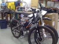
Now, I am further down the drive development road (4 years), and I finally have solved the double freewheel problem. The result is shown in the following pictures.


7d68a28a.jpg


9b7d7770.jpg


2a106569.jpg


ddff5e6b.jpg


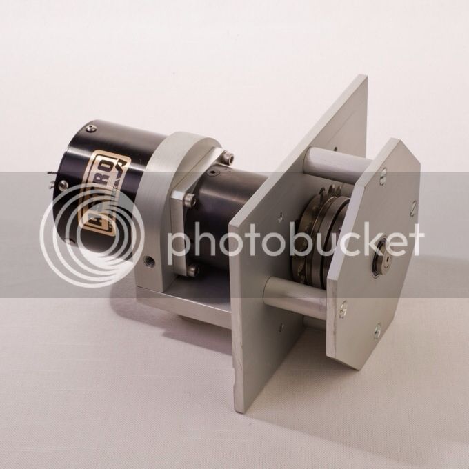
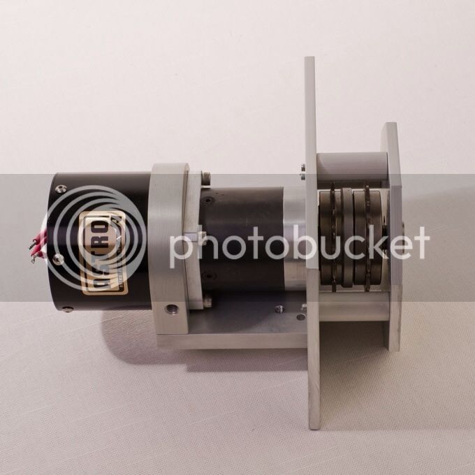
The motor is an Astro Flight 3210 6 turn Kv 250 rpm/volt, Rm 0.045 ohm, Io 1.00 Amp. The gearbox is a Neugart PLE 60, 20-1, precision 2 stage planetary. On the gearbox output shaft is a true double freewheel. Astro 3210 motors come in different winds for different voltages. The gearbox ratios can be selected for top speed.

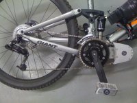
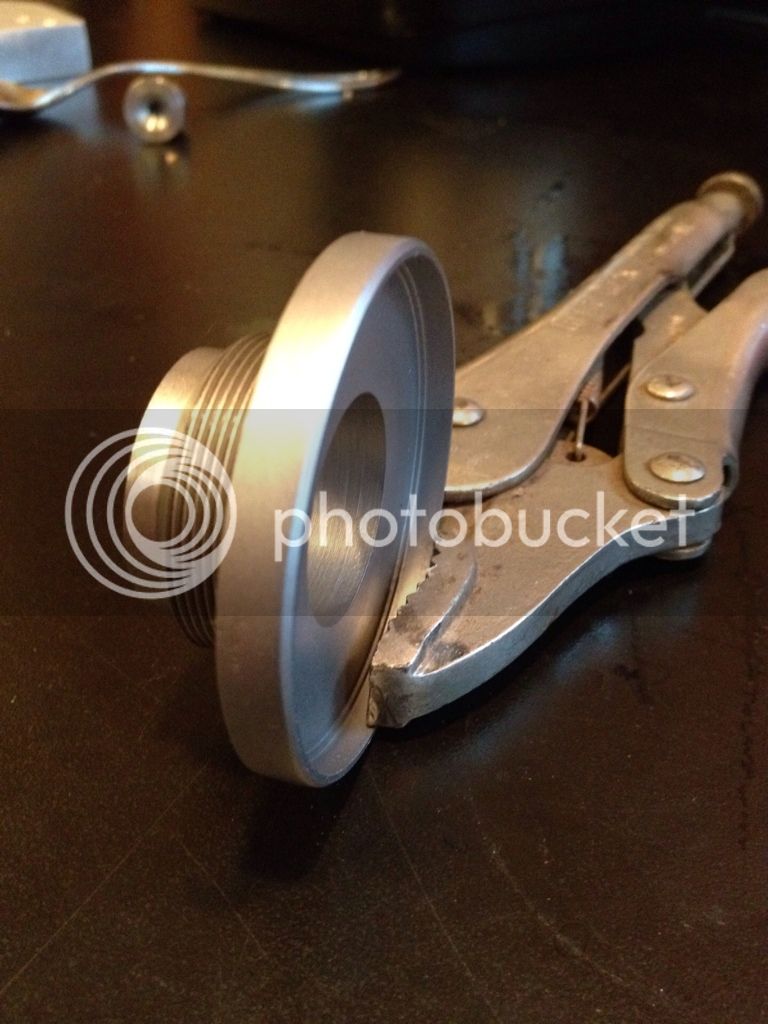
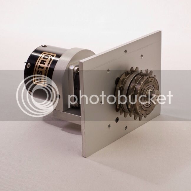
The two freewheels are mounted back to back, they engage in opposite directions. The inner freewheel, closest to the gearbox, drives the rear wheel. It is engaged when the motor is turning, and providing power. The outer freewheel is driven by the crankset. It freely rotates on the motor shaft, isolated by a roller bearing. When the rider provides power, the outer freewheel is engaged and drives the inner freewheel sprocket (only). The inner freewheel is isolated from the motor shaft, when driven this way, by its freewheel function. If you jump a chain, there is enough room between the sprockets, so the chains do not jam, but rotate freely on the shoulders of the freewheel. Josh Kerson has tested this double freewheel system extensively, on his Rans Stratus, with my original Astro 3210 drive system. He loves it, smooth operation, and no problems.


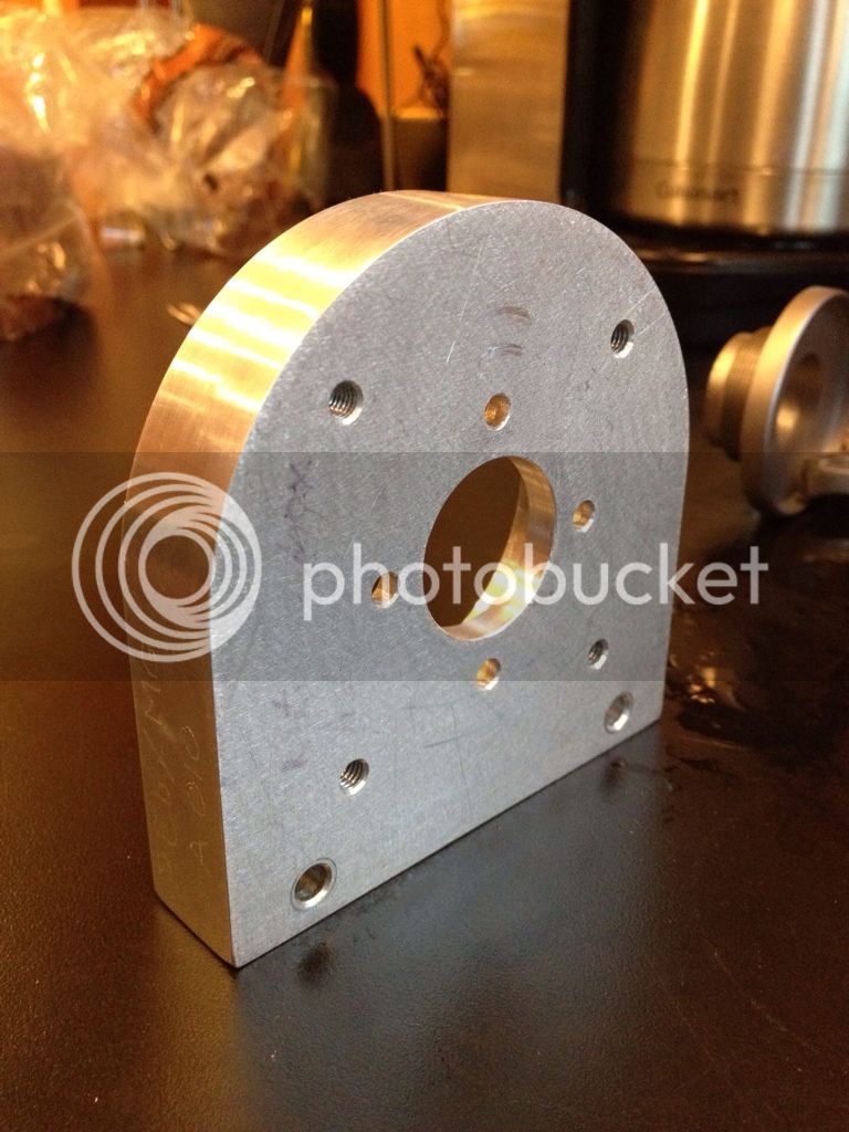
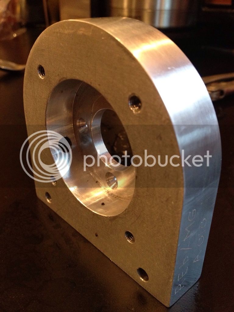
The front mounting plate is 5x7 inches. There are no mounting holes in the plate, as each application will be different. Tapped holes, in the mounting plate for the outer bearing support are every 45 degrees, so the four mounting spacers can be put in different positions to avoid chain interference.

This drive will mount up an Astro 3215, 3220, with very minor modifications. Any one wishing to test the power handling capability of a normal bicycle drive train, this is the system for you.

I am looking for testers, with a recumbent, who will mount, test, and publish results.
 
Nice! 8)

If the durability of the gearbox and freewheels is adequate, that looks like an ideal solution for many applications.

Any idea what the cost would be? Bet a good gearbox isn't cheap.
 
The list price of a two stage PLE 60 precision planetary gearbox is $465 as of a few months ago.

I am charging $1500 for the drive, minus electronics.

The gearbox is the same gearbox that successfully climbed Pikes Peak powering a bike and rider that weighted well over 300 pounds. Keep in mind that the drive load on a thru the gears system is much lighter than a hub motor or hard coupled drive. If you place the front wheel against a wall ( or start from stop in the highest gear ), have a battery that wll not significantly sag at 100 amps, have 160 amp Castle controller operating at 11 kHz, and do it enough times, you might get a stress fatigue failure of the gear teeth. That is if the controller doesn't burn up first, or there isn't a drive line failure. In these conditions the phase current will be over 1000 amps at part throttle.


04b4f36d.jpg


It is very hard to convey gearbox reliability in print. This motor gearbox combination has seen hundreds of hours of use, on several different bikes, without a single failure. I've had a few failures on the much smaller PLE 40 gearbox, when it is grossly abused.

The freewheels used are the new ACS crossfires. These freewheels are built like the Odyssey BMX freewheels. They are more rugged than the old ACS freewheels, and certainly much more rugged than Shimano freewheels.
 
Very interesting, Ron. I like the double-freewheel setup.

I recently used a six-turn Astro 3210 running through the gears at around 1000W also, for a distance challenge race. I was running it on 30V with power limited by a CA-LRC. There was no pedal input allowed in this particular race.

One thing that did surprise me is how well the derailleur coped with full-power upshifts and downshifts.

A question - aren't ACS freewheels usually relatively loud, as the BMX kids love their clicky-clicky noises? :roll:
 
Excellent concept ( double opposing free wheels) and well engineered with the outer bearing support.
..this is not a criticism , but is there a technical reason to use the Astro ? would any of the cheaper HK motors be suitable or is the design / mounting specific for the Astro only.
 
How have you locked the 2 freewheels together? Have you uses the raised lugs that the freewheel tool engages to remove a freewheel?

Looks like an excellent design, I like it a lot. Quality set up with tried and true parts.

Clay
 
Nice Work Ron,

This Double freewheel set up has been working well, on my Mid Drive Rans E bike conversion that we did a few years back.

This system works well for me, because it has no slip, and it's quiet. When riding at speed, pedaling along all you here is the wind,
your pedaling, and the light assist. The free wheels are quiet because they are not cogging, that is they are engaged. Sure, when
you are slowing down, and have stopped pedaling, you can here the free wheel, but it is as natural as can be, no louder than any
other bicycle that uses a traditional freewheel.

The big deal for me, is that this solution is several orders of magnitude more reliable than the slip clutch bearings found on a typical
Cyclone motor mid drive system. This has been able to take 750 watt surges, on an uphill start, in a low gear, with no problem. It preforms best
when you are at speed, and re engaging the motor and or pedals, and laying on the hammer for speed. It's right there, fully engaged and
rock steady like it has to be, so the rider can jump on those pedals if need be, confidently for performance riding.

I know this is a different system, but Ron, this Mountain drive rocks! This is the type of reliability needed to go off into the woods and chase
mountain bikers all over for the afternoon... :roll:

Peace, Josh K.
 

Attachments

  • IMG_1705.JPG
    IMG_1705.JPG
    144.5 KB · Views: 1,713
  • IMG_1711.JPG
    IMG_1711.JPG
    143.9 KB · Views: 5,291
quote: "than the slip clutch bearings found on a typical Cyclone motor mid drive system. "

Are you refering to the standard DICTA freewheel on the cranks ? or the freewheel on the motor ?

For the freewheel cranks the sick bikes eno and the and even better ACS crossfire seem to be reliable upgrades hence this is not a problem any more ?
 
Elegant setup! How are the sprockets on double freewheels coupled? By the spacer/antijam ring? Are you still using current limiting? Can that gearbox take the torque of a 3220 from a near standing start?
 
I don't understand how this is different then the link below other then using two acs free wheels instead of just one dicta freewheel and a screw on cog. Seems like using the screw on cog would be stronger??? I guess I just dont understand it. Is there still a clutch bearing against he shaft???


http://www.cyclone-e-bikes.tw/product.php?pid_for_show=3160

Could it be a sprag insert riding between the freewheels?

http://images.search.yahoo.com/images/view;_ylt=A2KJkK1xQehOrR4AmVSJzbkF;_ylu=X3oDMTBlMTQ4cGxyBHNlYwNzcgRzbGsDaW1n?back=http%3A%2F%2Fimages.search.yahoo.com%2Fsearch%2Fimages%3Fp%3Dsprag%2Bclutch%26fr2%3Dpiv-web%26tab%3Dorganic%26ri%3D26&w=230&h=230&imgurl=www.gmnbt.com%2Fimages%2Ff_b1_bild1.jpg&rurl=http%3A%2F%2Fwww.gmnbt.com%2Ffreewheel_technology.htm&size=19.2+KB&name=&p=sprag+clutch&oid=293dfc5fb5d9dc41aee5419d1129db92&fr2=piv-web&fr=&tt=&b=0&ni=48&no=26&tab=organic&ts=&sigr=11duopqga&sigb=12p98lanm&sigi=11361vld7&.crumb=a169aGgedaG
 
Hi Folks,

Okay, well I am glad that you guys have not had to deal with these challenges that I speak of.

The design that was leading the pack, for several years now, has been to use a slip roller clutch piece, under a single freewheel,
combined with a fixed cog. The fixed cog drove the rear wheel, and the free wheel accepted the rider input.
Unfortunately, That darn slip clutch, would let go, and you were not able to put motor power through it anymore, as it would
freewheel, in both directions...Sigh.

But, this double freewheel is a good solution to being able to apply power, through the pedals, and the motor, with no slip. It's
a really clever design, with tight tolerances, and smart machining to make this work. But, It's worth it for reliability.

Josh K.
 
Very nice looking setup. Too bad it's illegal here in NC or I might try the same thing myself.
 
ArtK said:
I don't understand how this is different then the link below other then using two acs free wheels instead of just one dicta freewheel and a screw on cog. Seems like using the screw on cog would be stronger??? I guess I just dont understand it. Is there still a clutch bearing against he shaft???


http://www.cyclone-e-bikes.tw/product.php?pid_for_show=3160

Could it be a sprag insert riding between the freewheels?

http://images.search.yahoo.com/images/view;_ylt=A2KJkK1xQehOrR4AmVSJzbkF;_ylu=X3oDMTBlMTQ4cGxyBHNlYwNzcgRzbGsDaW1n?back=http%3A%2F%2Fimages.search.yahoo.com%2Fsearch%2Fimages%3Fp%3Dsprag%2Bclutch%26fr2%3Dpiv-web%26tab%3Dorganic%26ri%3D26&w=230&h=230&imgurl=www.gmnbt.com%2Fimages%2Ff_b1_bild1.jpg&rurl=http%3A%2F%2Fwww.gmnbt.com%2Ffreewheel_technology.htm&size=19.2+KB&name=&p=sprag+clutch&oid=293dfc5fb5d9dc41aee5419d1129db92&fr2=piv-web&fr=&tt=&b=0&ni=48&no=26&tab=organic&ts=&sigr=11duopqga&sigb=12p98lanm&sigi=11361vld7&.crumb=a169aGgedaG

with the Cyclone cog/freewheel combo. both the motor and the pedal cogs run through the roller clutch to the motor shaft. all of the motor power goes through the roller/sprag clutch and it just can't take the power of these motors without failing. the roller/sprag clutch is the weak link.

from what i can see in the pictures and read in the text, this system is different because it eliminates the roller/sprag clutch. The inner/motor freewheel is directly connected to the gearbox output shaft and all of the power is fed only through that freewheel which is more capable of handling the power. and if it fails it is easy to replace. it is mounted backwards to lockup in the correct direction. the mechanism of the inner freewheel is replacing the Cyclone roller/sprag clutch.

the second freewheel that is powered by the pedals is mounted on a bearing so that it spins freely on the motor shaft. The tricky bit is to figure out what that steel ring between the 2 freewheels is hiding. this somehow couples the pedal freewheel to the sprocket and only the sprocket of the motor freewheel. I suspect that the pedal freewheel is threaded onto a collar attached to this ring and that the bearing for the motor shaft is pressed into the middle of the collar. the ring forms a cup that somehow is locked onto the hub of the sprocket of the inner/motor freewheel. that way when the motor is off, you don't drag the motor when you pedal.

The question is how does that cup lock onto the inner freewheel sprocket hub? is it welded? we need more information.

rick
 
fleebell said:
Very nice looking setup. Too bad it's illegal here in NC or I might try the same thing myself.
Why is it illegal? The power output level? (because that's easily fixed)
 
Nothing is illegal. O
[pre][/pre]
No sorry
Rated power
Burst power goes to infinty and the motor vaporizes like a wire constricts with current any you have a black hole or low energy zone
 
Looks super! How does it perform? Would you be willing to sell one, in parts or assembled? I've been looking for this for a long time.
 
The mid drive weight is just under 8.2 pounds.

Here is a picture of the coupling between the two freewheels.
1cefce2f.jpg

The next pictures shows the gearbox to motor adapter. The inner holes are for the motor mount screws, the outer holes are for the gearbox mounting screws. The outer holes are tapped. As you can see, the motor mount face will take most motors. A flat adapter plate would be the worst case. An Astro 3215, or 3220 will bolt right up, if you ream the motor mounting holes from a #6 to a #8 screw size. The hole centers are the same.

09657ca9.jpg

0e4cb45c.jpg

The gearbox coupling takes a 14 mm shaft, with adapter bushings available from Neugart for 0.5 inch on down, in metric or English sizes. The shaft length has to 1.00 inches, or slightly less, from the surface that mounts to the motor/gearbox adapter.

In most cases the gearbox can handle an Astro 3215, or 3220. The only restriction is that you have to be very careful to start out in a low gear. Under motor stall conditions and partial throttle, you can strip the gearbox. You also have to consider if the bike drive train can handle the torque. No guarantees when using alternate motors!

The drive and the major components are for sale, and in stock. At present, I am low on Astro 3210's. It takes 4 to 6 weeks for delivery of motors. The drive is $1500 minus electronics. PM me for more info.
 
Ron Z said:
The mid drive weight is just under 8.2 pounds.

Here is a picture of the coupling between the two freewheels.
1cefce2f.jpg

<snip>

so it is just a simple interference fit between the coupling and the inner freewheel. is that secure enough for the pedal input?

rick
 
The coupler to inner freewheel joint is a light interference fit used along with a special bonding agent, waterproof, and oil proof, made especially for applications like this. For torque, that's a long bond line.

I asked Josh to try and break the joint. He is a large, strong guy, who is an avid cyclist. He did not break it.
 
I forgot to mention that motor phase current control, as in my 500 watt mid drive, is not necessary or implemented, on the 1000 watt mid drive, or 750 watt chain puller. The Neugart PLE 60 is rugged enough to handle the torque.
 
Back
Top