New serious Offroad bike : The Chainer

bzhwindtalker

100 kW
Joined
Dec 1, 2008
Messages
1,807
Location
Lyon, France
Hello all!
I'm back for more offroad action.
The old bike with a pimped up conshis mid drive got me into those systems, and I enjoy riding this bike evry time i can, pulling wheelies with ease and keeping the front wheel in the air on the trails, bashing HARD with awesome torque and control, and a 40mph(65kph) top speed on flat, using a very basic hub and heavy headway cells.

This is what it is capable of :
[youtube]kq8Ii4XYLGM[/youtube]

270840_401877499848510_845331033_n.jpg


You can find the build thread here : http://endless-sphere.com/forums/viewtopic.php?f=28&t=37805
Long story short, the frame failed several times, proving that a frame suited to a mid drive is hard to find. The increased torque of the motor causes frame twist and frocks up the suspension action if the chain pull point is not good.

Building my own :D

chainer 1.png

I have been thinking about this for a long time, now I have some free time this summer to get this done. At this point what is holding me from riding even harder is the chassis. Power to weight is right, range is OK but the chassis integration sucks. I canth pedal properly, and I feel the rear end twisting from chain traction !

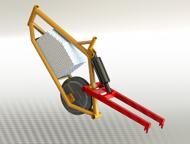
The new frame is somewhat overly complicated. It has got an overruning pivot point that doubles up as a jackshaft, 3 chains, and a jackshaft hub motor in frame.

This is the best set-up I came up with that offered the folowing features :
-No chain length variation
-Use of standard bike components
-Any rear hub motor with no modifications
-No induced frame/swingarm flex

Issues I can think of :
-Lateral flex of the frame at the pivot point and weld fatigue
-2 fast moving chains > dangerous
-Wide swingarm between the rider's legs
-Not cheap to make


The jackshaft was complicated to design. Hope I got it right! the internal bearings are 32x20x7, the external ones are 28x12x8.

The motor will receive pedal power from the right side, like in a standard system. I will use the left side disc mount to power the jackshaft with a half link bike chain. The jackshaft will then get the power back to the right side, perfectly in line with the rear cassette, with a pull point as close as possible to the pivot point.

chainer2.png

Lost yet? :p

This is what I will use on the two sides of the JS :

http://cgi.ebay.fr/ws/eBayISAPI.dll...eName=STRK:MEWNX:IT&_trksid=p3984.m1439.l2649

The 10t sprocket will be on the cassette side. Massive undergear 8)

montage lowQ.jpg

Please comment, I need some input on this!

The first hub I will try is a fast wind BPM 500w on 14s Li-mn if I find a suitable cell, li-po otherwise. I know I should bump the voltage up to 75v to get full potential out of this kind of motor, but I like the bms battery KU123 controlers and they are limited to 63v. I may get a Lyen 6 fet for more peeps and less load on the motor. I will next try a Cute 500W.

This bike will be tuned for 2500w max, maybe less if the motor is fast to spin up. The frame will hold about 550wh, enough for 30-35min of hard offroad fun. My currrent bike uses about 25wh/km at a good pace offroad.

I will try to post my drawings for the overrunning pivot point, I am guessing about 250€ for the machined parts and basic steel tubing, I will then tack weld the frame and get it welded by a pro.

Any input guys?
 
Very nice, I've been thinking right along those lines for an RC motor reduction, it would need a stage more reduction before the jackshaft though. The only thing that's sketchy with that, is the TEN! :shock: tooth chainring. I think that is a failure point. It will be a chain stretcher, probably skip, and make noise. How fast are you planning for the jackshaft rpm? How fast is the fast wind motor? I think slow the jackshaft down a bit, put a 16 tooth and your good. Overall very nice. Might have a go myself! Actually, I have the aluminum tubing to make mine out of, need to get going on it. Great videos by the way! And your 2 bikes have been cool also. I think this one will be far better. Good luck, watching with great interest. :D
 
If you have to go to a ten tooth, just convert to 219 o-ring chain. I've got a ten tooth 219 driver on my bike and after 1400ish miles, there is zero visible wear. I also haven't had to re-tension the chain. :wink:
 
Yeah 10t will probably be too slow anyway! I can't use 219 because I need gears to make the most of limited power. I have the hardware to get the final stage in a 12/92t #219 configuration if I ever need to pull a train with my bike :) If 10t works out too slow/noisy/bad, I will weld a 13 or 15t sprocket on it.

Opinions on my Jackshaft design? I fear it will put too much stress on the bearings...
 
Oh yeah : the JS will spinn at about 500rpm, very close to the motor rpm. I figured that as the rear wheel already has a 11t sprocket that will only be used at higth speed (lower torque) but the chain load will still be really higth with a 10t sprocket, 12-13 would be more suited. I currently use 15 with a consequent misalignment, no visible wear.

I only need 45kph for the kind of riding I love. But I want even more torque than the current bike, that has a 35kph first speed.

I'm giving the parts to make to a machine shop tonight, and hopefully they will have the tubing I need too!

Adam
 
bzhwindtalker said:
Opinions on my Jackshaft design? I fear it will put too much stress on the bearings...

It's not the bearings that I'd worry about. The axle is going to have a tough life there. The long unsupported span between the swing arm bearing and the axle bearing isn't good. A standard bike part probably isn't going to do the job right there. It took me three months to design my jackshaft pivot/swing arm pivot and it's using 20mm id dual row angular contact bearings. Aside from all the belt drive design stuff, figuring the jackshaft out has been the toughest part of the design work on my build.
 
A Brooklyn Machine Works inspired jackshaft!!!

Trusted method, should be awesome!!

D
 
Looks good to me, the only possible problem may come during assembly or to be more precise dissasembly, to get the swing arm onto the JS you will have to put it in position and then press the outer bearings into place followed by the securing bolts, to take it apart again you will need to pull the bearings out, how will you do this? You may need to have the swing arm secured to the bearings with split clamps, Bomber style.
Keep the front final drive sprocket as small as poss, if you need to alter the gearing you have many other sprockets you could change to do this.

An alternative method maybe to use shoulder bolts through the outer bearings which sleeve inside a bored diameter inside the ends of the JS.
 
If your motor is spinning 500 rpm your pedals will not be able to help. They will only spin the motor at about 3 times cadence (about 80-90rpm), so that's 270. Have the pedals 3 to 1 to the jack shaft, and the motor 1 to 2 to the jack shaft, which would now spin about 250 rpm, and match motor and pedal speed together. Now you can do a more reasonable 18-20 tooth on the jack shaft. Downsides, you have to figure out how to fit another freewheel on the jack shaft. So worded another way, pedal chain to jack shaft (on left or right side), motor chain to jack shaft (on left side), both on freewheels, and then cog (on right side of jack shaft) to rear cassette. Added bonus, you'll know what the optimum motor gear is just by pedaling. :mrgreen: Oh plus you could use a narrow front hub motor! (with disk brake holes, of course). Also it would allow the jackshaft to be a larger diameter. 0.57" is pretty small
 
My planned solution to get pedal input stepped up enough is to use #25 chain from the crank to the JS. Then I can go with a tiny diameter sprocket on the JS for the pedal input.
 
My guess would be a custom 25 chain sprocket bolted to a flanged freewheel.
 
I planned on using a 53/16 sprocket arrangement on the pedal side of the motor. I could use a cassette and get down to 13 or 11t on the motor... Then with a 14t on the JS I could efectively pedal at fast speeds, with the two lowest gear being overgear (53/13-14/11) does not seem ridiculous to me, even with 10t on the JS.

I found a solution for the assembly : I could have the axle made hollow and have the 12mm part slid into it, like that I could get it in and out eazy. I don't think doing so would weaken the system, and I could use strong stub for the 12Mm part. Does this seems ok?
 
wildharemtbkr said:
John in CR, how will you do a freewheel for the cranks with the #25 chain?

It would depend on the implementation, but I have different parts such as one way bearings from some friction drive rollers and a freewheeling crank rig. I'd want to try the one way bearing or a pair of them as the first option due to the silence of the freewheel action.
 
John in CR said:
wildharemtbkr said:
John in CR, how will you do a freewheel for the cranks with the #25 chain?

It would depend on the implementation, but I have different parts such as one way bearings from some friction drive rollers and a freewheeling crank rig. I'd want to try the one way bearing or a pair of them as the first option due to the silence of the freewheel action.

hey john can i ask where you're getting 'em from? I'm thinking of doing the same myself... also, as to doubling them up... does that reliably double their torque handling?
 
I ordered the steel, and I got the quote for all my JS parts+ machined head tube. At 245€, it's far than cheap but at least my estimate was good!
 
Allrgth the JS parts are paid, I used and online machine shop service, let's hope they work well... At least they are used to work for consumers and it is their main market. I added the zip file with the last design that will make assembly and disasembly easy with the two axles.


The frame will not really have this shape (the drawing on the first page is more accurate, with straight down tubes) but this shows the 3d layout.

7326708908_f32eabfa06_b.jpg


I was wondering what tubing sises and thickness would you guys recommend? The top tube will be 30mmx2, and the down tubes will be 25mmx2 but I feel like the down tubes don't need to be that strong/heavy. I think 20x1,5 could do the job. Remember the frame will be made of mild steel... I had some quality ST37 steel ordered, but I canceled my order because of the ridiculous delivery time (I waited for 2 months :shock: )


I hope to have a rolling frame by August :)
Adam
 

Attachments

  • devis Adam Mercier.zip
    407.5 KB · Views: 122
My tubes have shipped today, I went with 25mm*2 for the down tubes. This will be heavy :/ I looked up the suspention action, and with a 215/63mm stroke shock I will have about 165mm of rear travel :)

Does the suspension design look ok?

I know a more evoluted design would be way better, but I really can't be bothered...
I also modified the frame to have two tubes joining at the JS and minimise frame lateral flex.

suspention design.png


Oh yeah, look at this too!
scaled.php


Looks similar but the suspention angles are not quite the same...
 
I would go with CoMO tube from Columbus , very strong and light ,
here is the link http://www.trafiltubi.com/doc/eng/chisiamo1.htm .
they have many tubes and size on stock , so you should find yours .
generally thickness on these tubes is 0,7-0,9 mm .
in some cases they also have thicker at top and bottom and thinner in the middle section , where there is less stress .
Maybe you can try the frame with normal steel , to see is size and shape is OK .
then turn to CoMo .

Rgs Renago
 
Thanks for the link, they have a "FAST Shipment Wharehouse" that seems to stock some common cromo tubing, in easily weldable thickness. I doubt they do ship to individuals but it's worth looking up...

Do you recon a small oxygen-butane blow lamp could be used to brase lets say 35x1,5mm joints? I want to get into brasing as it seems to be a nice alternative to TIG for DIY bike building.
 
all old bike were braised , because at that time TIG welding was costy and not so commune .
If you brase the joints I would not go over 1 mm thickness for joints .
pls consider that the final thickness will be the joint and the wall thickness , in CoMo steel , so aprox 2,2 mm !!!
that is enough for a space frame for rally car !
no need for over building .
save all weight possible

Renago
 
Hey

Nice bike you are planing. I´m planing a similiar (in general at least) frame layout.
I found some intersesting bike designs.
The bike in the link below is selfmade too but Tig welded

http://www.youtube.com/watch?v=0JQi1t2anXM
(was inspired by the Superco Silencer really nice bike as well)

Here a self made frame made from aluminium

http://www.downhillschrott.com/ Can not copy the correct link but go to: Bastelseite / Downhillrahmen im Selbsbau /(scroll down->) Weitere Bilder

The all seem to have a perpendicular swingarm to headtube layout. And a rod to avoid wheel movement when braking.
 
Back
Top