Chopper bike with 93% eff motor

Bluefang

10 kW
Joined
Aug 27, 2010
Messages
589
Location
Australia, Goldcoast
Hey guys and girls,
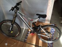
A while ago i bought one of the 93% efficiancy motors that John from CR was selling and i decided to mod it out to a reasonable level to allow me to push alot of power through the motor. Along with that i had a sample cruiser/chopper/lowrider bike that i imported from china that had some cosmetic damage to the frame so i can not sell it so been such a long bike it hopefully will be unable to flip me off the back with the large amount of power i am hoping to have.

With the motor i have had the flange cut off it so it can be used as a mid drive. With the switching mechanism in the motor it has been removed and i have moved one of the bearings inwards so i could mount a adapter to mount a sprocket on the motor case. The sprocket is 22T 219 high quality go kart chain and the rear will be ~90T. For the rear wheel atm it is a manual Nuvinci hub with the power running into the disk brake side of the hub, with its internal freewheel and robust design i hope it will survive(so i can pedal the bike if it ever brakes down or i need to go a long distance). The front and rear wheels atm are normal 26" rims and wheels but i anticipate changing the rim and tire on the rear to a 21" motorbike combo and changing the front wheel to a 29" bicycle DH wheel with a 12mm axle and moto disc for braking.
http://www.endless-sphere.com/forums/viewtopic.php?f=31&t=40859

IMAG0348.jpg
View attachment 2
View attachment 1
IMAG0353.jpg
 
The questions i have atm are, is the nuvinci hub likely to hold up to constant freewheeling and power input of up to 30kw thru the disk brake side?

With the fan linked, should i remove some of the vanes as it will be spinning at ~2500rpm once i have the bike running on 150V? Or the more the merrier?
 
Cut away the old seat post that interfered with where the motor was going and i also wanted a proper sprung seat as its a hard tail bike. Also made modified dropouts, they are cut out of 6mm plate and move the wheel further back and raise the rear of the bike a bit to reduce the rake on the front.

IMAG0354.jpg
 
Bike's looking great! Can you show us how the sprocket is done, or is it just slid on the axle for now? Let's fully discuss the fan thing before you start hacking. ie What is the circuit of air flow, from intake thru exhaust?

The weather is finally changing here and we're emerging from wet season, so time for me to catch up.

John
 
The sprocket is welded onto the case of the motor, fyi the case is some high quality hard steel. After realizing there is no need to cut the side of the case off, its weight is negligible compared to the core, i decided to use it to do a solid mount for the sprocket. There is a machined piece that mounts from inside the case and sticks out from the bearing opening. This is welded in place and the it was lathed down so that the sprocket was a slip on fit, 1" bore. Then the hole for the shaft was borred to 20mm and the shaft had some taken off it to make if fit with abit of room to spare. All this has pushed the bearing in abit which is fine since i removed all the switching mech from the motor.

For the fan, i am planing to have air intake on the alloy side and outlet on the chain side. I will cover all the holes in the stator to force the air through the windings. With the outlet side i have not decided on how to do the holes so i am open to suggestions. Option one is to drill holes to match the number of vanes around the outer edge of the side angled to the outside of the motor. With the bottom of the fan been open this will suck some air into the fan which in turn will draw the air out of the motor. The other option is to have less holes closer to the center of the motor and delete some of the vanes so they match the number of holes. My machinist has warned me about the metal been really strong so i would like to keep it simple and just drill the holes and not do slots.
IMAG0355.jpgIMAG0356.jpgView attachment 2IMAG0358.jpgIMAG0359.jpg
 
I really like the way the sprocket is done. I realize now that I can't use 219 chain, since I need a much larger diameter since I want to mount it at the root of the bearing bulge on the steel side.

My concerns about the fan are:

Noise- Mount that puppy on a drill and see how much noise it makes.

Flow- A centrifugal fan of that size is going to want to move a lot of air a 2krpm+. The magnetic gap has a cross sectional area of only about 3.5cm2 (maybe 4 counting the slots, and the magnets spinning by will cause turbulence that further restricts flow. Check into centrifugal fan operation, but I think flow drops way way off when starved of air. Their flow is really created near the tips of the blades (think of a squirrel cage fan, which only has tips), so you could put exhaust holes (say 8-10mm) at the corner of the extreme perimeter. Then you can leave some flow through the center and still get flow through the gap. You would need to trim the blades at an angle to fit against the motor shell, but you probably need to do that anyway. I worry about using centrifugal force to create flow, but also fight against centrifugal flow after it goes through the gap to go over the end windings and to exhaust the shell at a point of less radius than the windings then back to the blade tips. Even just having a 90° bend of an air duct within 1 diameter's distance of a centrifugal fan's intake can reduce flow significantly.

Another consideration is how the air flows inside the motor. It will always follow the path of least resistance. My view is that if left to it's own devices the air flow inside our hubmotors will naturally follow the covers. This will be even more true on the tapered steel side because there's more space between the stator and sides with the switching mechanism removed. I believe the blades I put inside my side covers that are angled to deflect air away from the sides toward the stator play a big role in my success with ventilation. 6 or 8 fairly small blades that pass quite close to the end windings create small puffs of air on them, and at double the rpms you'll be running compared to what I've run that has to dramatically affect the convective heat transfer coefficient compared to an air flow mostly out near the side covers. Those blades also help ensure the air is spinning and turbulent where it is needed most instead of mostly at the perimeter.

You can always try the big fan later but I'd just go with holes in the motor and blades inside. I say holes, but I plan to do slots on both intake and exhaust making entry of large debris impossible. Intake would extend to a lesser perimeter than the end windings, so all the flow thru the gap must pass over the end windings on that side. I will cut numerous angled slots for a true blade shape right at the steel corner, taking care to cool it frequently so I don't harm the magnets or their adhesive. Both sides will get blades to deflect air directly at the end windings.

Slots will be easier than holes with this motor, and another reason I like them is that they are far less likely to whistle than holes. I haven't had a whistling problem, but under the right cross winds one of my motors has whistled a bit.

If you want to wait, I will commit to cutting these slots on a motor shell this weekend and post picks, to identify problems first, and show you exactly what I mean. It will give you a cleaner look and less noise, and if you have heat issues you can still put more holes in the steel side and add that fan.

Here are the covers of my best ventilation to date, which was on the original hubmonster, and it has one sided intake with exhaust out of the other side. The blades made of AL sheet are bolted and epoxied to the covers to ensure they don't ever rattle or come off, which would destroy the motor.

John

SuperV with Hubmonster inside covers.JPG
 
How are you cutting the slots to think it will be easier then drilling holes with a cobalt drill bit? To me a grinder would probably be too big and a dremel would take for ever :)

Your superV covers are about perfect for me, nice and simple and they will work with my theory for having the fan move air accross the holes and sucking the air out of the motor that way :) Tho this time i will put the little blades in side the covers too.
 
Im super excited to see this build progressing. I will be doing the exact same thing on a dual sus bike. I plan to mount the motor low and on the swingarm real close to the pivot point (1/2diameter of motor case). to control chain growth issues.

Really cool frame. What will be your final drive ratio, what voltage and controller, what sprocket source?

I need middrive, im getting to hate hub motors because of the weight in the wrong spot, cramps my riding style which is FreERiDE!!! and cost me a fortune in rims. And the problem just got worse with my cromotor

This is gonna be AwesomE!!
PeaCe
mike
 
I'm going to use a thin cutting disc on an angle grinder. If anything, I think the thinnest disks for cutting stainless are too thin, but that's what I'll start with...the cast steel is hard. Keeping it cool is my only concern. Getting shavings out will be a pain, so I'm thinking tape over the mags, and then put some double sided tape around the inside to catch most of it.

Dremel...no f'ing way. I uses a dremel to do pretty slot vents on an AL cover and that took forever and a mountain of discs. It would take a lifetime on that cast steel.

I was looking at the open stator I have and on the wire side there's plenty of room for blades. That side goes on pretty easily, so with the bell housing off I can do the blades and adjust them so they have minimal clearance for maximum effect. Note the angle on mine, and how they don't stay perpendicular to the axle like a vane in a fan. To some extent I want them to act like a blade, but even more I want them to just deflect any flow trying to hug that smooth side and send it directly at the end windings.

I'm going to cut my slots this weekend. I do want to angle them, though maybe not necessary on the exhaust since we can easily shield the flow from influence from outside flow. Centrifugal fan blades can be straight, reverse curve, or forward curve. I want to go reverse curve, because while it sacrifices flow, they are more quiet, and better at pulling a pressure which I believe is important due to our flow restrictions. That means I have to decide definitively which side to use as the wire side.

John
 
Bluefang !!! :idea: :idea: :idea: :idea:

Your method for installing that sprocket is f'ing perfect for mounting freewheel threading. Hack a cheap steel rear hub and turn its spoke flange down to the OD of the bearing. Slide it in and tack weld in place on the outside. I just verified the OD of the threads is smaller than the OD of the bearing. It will work on the AL side too, but the thicker material may require a narrower bearing with the same ID and OD.

Those doing the same, don't forget to trim the bearing limit on the axle for the same side.

Nice, neat, and simple. I knew you guys would help come up with great ideas for all. :mrgreen:

Thanks,

John
 
Are you sealing off the flow thru the stator with your mods? Forcing the air directly over the windings, i wouldnt have thought there would be much point to blades on the exhaust side?

I think for holes i will just stick to 12mm angled drill holes but i will wait untill you have played with yours if your planing to do it this week end.

Hydro-one, what power level are you after? anything under 2kw and you cant go past the GNG drive with a few tweaks that alot of people have been looking at recently. And if you changed the belt to chain and increased the reduction ratio then you would have a even more powerful system. The motor i am modding comes in stock form something that will do 6kw all day long and a internal 2 speed switching mech, with the mods i am doing i am aiming for bursts of >20kw, but saying that its wayyyy to heavy for freeride, unless your talking pitbike or dirtbike level. I ll be testing a controller John is hoping to get soon from one of his sources that should be good for at least 30S and i ll see how it goes at 36s :twisted:
 
Your method for installing that sprocket is f'ing perfect for mounting freewheel threading. Hack a cheap steel rear hub and turn its spoke flange down to the OD of the bearing. Slide it in and tack weld in place on the outside. I just verified the OD of the threads is smaller than the OD of the bearing. It will work on the AL side too, but the thicker material may require a narrower bearing with the same ID and OD.

I am happy to be of some help :) Damn good thing you thought of that cause i am thinking of getting another one of these motors to run a 10kw switching at a later stage. 1/2 link BMX chain will hold up to it. Tho i wont be using a free wheel tho :) regen ftw
 
Well u see those guys with the freestyle motos with the high jump ramp and all that, i think i can do that but with 80 pound bike with this motor and moded dh frame. I want 20kw to!! im thinking a 24fet 4115 at 30s, geared appropriatly? i cant afford anything else

Im thinking : my buddy weighs 40 pounds more than me. less than this motor. i will build around the motor like lighting motors.

How will this compare to a big astro? should be much more controllable with the right controller no? and much higher power continous?
 
hydro-one, all the information your after is http://www.endless-sphere.com/forums/viewtopic.php?f=31&t=40859. Its bigger and much lower KV then a astro. We are still to find out how much power it can take. But it should be pretty damn good.

Kinda sucks, i spent an hour mocking up how to do the motor mount and then i realized that i had not moved the seat stay out of the way of the chain line. pfft :( All modified now so back to mocking up the motor mount....after lunch :pancake:
 
I will be following this thread. I'm thinking of strapping the same motor on my next build. Single reduction to crank or direct left side drive. Will have to do some mock-ups to see if it will fit somewhere.
 

Attachments

  • photo 1small.jpg
    photo 1small.jpg
    83.6 KB · Views: 3,642
Bluefang said:
Are you sealing off the flow thru the stator with your mods? Forcing the air directly over the windings, i wouldnt have thought there would be much point to blades on the exhaust side?

I think for holes i will just stick to 12mm angled drill holes but i will wait untill you have played with yours if your planing to do it this week end.

I'm going to keep the 2 speed switching on the motor I cut this weekend, and the 2 speed mech really blocks up any flow through the center, so first I'm going to look at drilling some holes in the drilling mech to allow some flow through the center for a fresh air supply to cool both the switching contacts and the end windings on the exhaust side. If that doesn't look practical, then I will add a small amount of intake area on the exhaust side with holes right at the bearing bulge to take some air right in on top of switching mech, because I see it as the main current limit for a stock motor. I want to keep that exhaust side intake small to ensure I still get as much flow as possible through the magnetic gap, because on a 50mm wide stator that is such a big part of the surface area of the stator and it's the heat source closest to the magnets.

To me the blades I use would be quite beneficial even to a sealed motor. With them passing so close to the end windings it's like the difference in cooling your bowl of soup just letting it sit there on the table vs blowing directly in it. You can feel the greater heat rejection in the warm air back at your face as you create a turbulent flow at the hot surface of the soup when you blow.

A few weeks ago I got my mid-drive Mini-Monster almost hot enough to trip the 95°C thermistor on the stator iron for the first time ever. It occurred right at the end of a long generally uphill ride into a stiff headwind. Most of the climb (nothing steep and only 300m net) was in the first 20km and I was riding harder, but mostly at cruise at 40-60kph and a handful of stops, and the motor was fine at that point when I stopped to check things when I got to the flatter area of downtown. The motor shell was warm, not hot, maybe 50-55°C. Traffic was horrendous in downtown leaving no place to go much of the time even on a bike, and I left the windings switch in high but rode fairly gently. After 5-6km at low speed and 20-30 full stop easy starts, I couldn't believe how hot the motor was when I stopped. It took a good 15 minutes for the motor shell to get down to my more than a few seconds hand limit of 65°C. That 12lb stator holds a lot of heat for a long time with a layer of air as insulation between it and the outer shell.

I can't stress how hard repetitive full stop starts are on any motor, because they all start at 0 efficiency. I want to do the identical ride with my basic ventilation strategy in place, which uses a natural centrifugal flow to pull air into the motor and exhaust it at the perimeter, and at the same time creating as much turbulence in the flow as possible right where it is most effective at the exposed copper of the end windings.

Hopefully the ventilation slots are pretty easy to cut into that steel corner, because I want to demonstrate to others how effective ventilation can be without opening the motor to large debris getting in. Look at the ventilation slots on almost any well designed electric motor that isn't sealed. We have the advantage that our outer shell spins, so slotted exhaust vents can be shaped into a true blade shape. A centrifugal fan 6.8" in diameter turning at 2krpm can move an incredible amount of air. :mrgreen:

Sorry another book-like post...good info though...I think. :|

John
 
Bluefang said:
hydro-one, all the information your after is http://www.endless-sphere.com/forums/viewtopic.php?f=31&t=40859. Its bigger and much lower KV then a astro. We are still to find out how much power it can take. But it should be pretty damn good.

Kinda sucks, i spent an hour mocking up how to do the motor mount and then i realized that i had not moved the seat stay out of the way of the chain line. pfft :( All modified now so back to mocking up the motor mount....after lunch :pancake:

Are you going to make the mount fixed or adjustable? I ask because I made mine fixed, and I got lucky that it was aligned well enough to achieve a dead straight chain. I found that a dead straight chain plus a firmly sprung idler were critical for a surprisingly quiet chain.

John
 
The fork is from a medium quality chinese pitbike, something like 100cc. Go to your local pit bike/go kart seller and he will probably have a few out the back he cant get rid off. I got lucky and my local go kart shop has a ton of them and he gave me one pretty cheap. Only the dampening is adjustable but you can get others with all the bells and whisles, stick to the smallish pit bikes as they have a 1"steerer tube :mrgreen: Or go in and measure to get it perfect

With the venting i am starting to understand better from where your approaching this from. It sounds good all i can hope is that if i stick my fan on the outside of the motor too it may help even more and hopefully it doesnt make much noise, hopefully a nice quiet turbine like whisle :p If i have this much power to play with i want to have some noise too :) not much but abit :oops:

The mount will be adjustable by about 5mm side to side, and about 20mm back and forth. If that fails to get it right the rear sprocket is easily adjustable, kinda hoping to not need a tensioner as i would like to use the regen at a fairly high level. Still need to figure out how to mount the seat as i need to come about 3" back and 2" up from where the motor mount stops. May have to build some sort of triangulated structure that also ties in with the dropouts at the back to mount the seat springs and hold the motor in place once its under power :)
 
To bring saddles rearward I've had good luck turning steel seat tubes into kinda an L shape by cutting them at an angle, and cutting a strong piece of steel in the L shape to fit inside the seat tube pieces. Then I weld it into the vertical tube first, and fit the rearward extending tube and weld it in from the end as well as weld the seam.

Pit bike shops LOL!! This is still a developing country, not a developed one. There's probably a cart parts shop out at the race track that also has a cart track, but I can just imagine the high prices. It's only 5 miles from the house, and I need to run out there to find out when the drag setup runs, since before too long I'll be ready to get some time slips. Plus the guy never did call me back about pricing to rent the cart track and see if we can put together an ebike race.

The sun is up now, so let me know if you want pics.
 
well he wasnt a pit bike shop, more of a go kart, off road buggy, dirt bike shop. Try your luck as some older motorbikes use 1"steeres he may just have a pile of them just for you to play with.

The seat i have is actually for a bobber motorbike conversion, so it has a pivot joint at the front and the rear is suported by 2 springs about 6" apart and 9" behind the pivot point. Will make for a nice comfortable ride i hope. Its a bugger atm as i am at work so i can not go out and play with the bike :(
 
BTW, with the FW threading I wasn't thinking of power, but instead for the pedal input, especially the guys running in-wheel. It's gonna take a jackshaft for 2 stages to get up to the these rpms. :twisted:

For forks, I already have some moto solutions...heavy. I've got a Marzocchi Monster 888's on the way though. I picked up 2 refurbs with brand new lowers for $600 including shipping. My son got his already and says it's a beauty. I'm waiting for mine to arrive before I can refer everyone to them.

I've got an ebike portable solar charging rig in the works too with no converter losses. It will be segmented to allow whatever voltage desired and add parallel strings for more current. Plus it will even balance charge lifepo4 or lipo packs. Then you guys can take your bikes into the outback for full weekends of fun without pedaling. :mrgreen:

John
 
Changed the chain line, moved the seat stay 1" out wider on that side and worked on building some supports for the motor. Using handle bar supports from a pit bike atm, just need some thin metal to have a better clamping grip and then i ll drill a bolt into the shaft slightly to lock it in place once i am happy with everything. Tried mocking up the seat but the motor is slightly higher now so i will have to change the seat a fraction until i find out how much it will move when i hit large bumps. So waiting for the post to arrive...lots of post soon. :)

IMAG0360.jpg
IMAG0361.jpg
 
Bluefang said:
Changed the chain line, moved the seat stay 1" out wider on that side and worked on building some supports for the motor. Using handle bar supports from a pit bike atm, just need some thin metal to have a better clamping grip and then i ll drill a bolt into the shaft slightly to lock it in place once i am happy with everything. Tried mocking up the seat but the motor is slightly higher now so i will have to change the seat a fraction until i find out how much it will move when i hit large bumps. So waiting for the post to arrive...lots of post soon. :)

View attachment 2
View attachment 1


hey bf do you know or can you measure the diam of the motor at the point you're mounting the sprocket to?

Untitled.png

also, is there anything preventing mounting a sprocket to the other side, flipping the motor and running it in reverse (ie still as a left hand drive? )


edit
and john, what power (volts/amps) and effective rim size did you have during that 'overheat' situation?

cheers.
 
Back
Top