Yet another electric trike

yawstick

100 W
Joined
Oct 31, 2013
Messages
122
Location
Spartanburg SC
My first post here.... lots of good info here... I'm a long time recumbent trike fan and have a Catrike Speed and a home built trike as well. Some years ago I was looking at some of the hub motors but never bit the bullet. I recently happened on some videos of trikes with RC airplane type motor conversions and now have the fever for rolling my own.

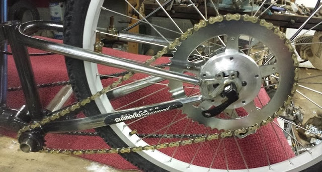
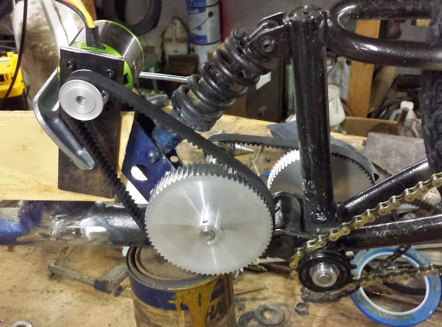
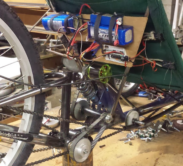
I already had a 110 gas equivalent motor and going to use a two stage reduction with 5M HTD belt drive off the motor and BMX style freewheel driving a chainring mounted on the disc brake rotor mount on the rear hub. I've seen it somewhere but a recent search failed to turn up the spec for a standard disc brake rotor mounting holes. If someone could point me in the right direction on that I would appreciate it. I have ordered most of the parts to put this together but going to make an adapter for the brake rotor mount to a chainring. I have a lathe and milling machine at home and also access a milling machine at work with a digital readout that can do bolt circles, but need the size of the bolt pattern.
 
ISO disc rotor BCD is 44mm.
Some of the rear hub motor adapters use a 48mm BCD disc rotor.
 
I'm still waiting of a new rear wheel with disc brake hub but have managed to fabricate some of the parts. The final design still a bit up in the air but a have posted some pics and info here. http://electricktrike.blogspot.com/
 
You have an interesting project started, and it looks like you have the ability to finish it and improve on it. I will be following your posts. I am in the process of building my third trike, it will be my first with power assist, probably a friction drive. Thanks for taking the time to show us your work.
 
Your comments and the complexities of integrating motor with rear suspension have caused me to give the friction drive a lot more thought.... particularly for the short term. I only have a few minutes riding time on the friction drive but enough to see the need for some mods. The motor I'm using really needs the 44 volts to develop decent power. I will be testing that come this weekend. The tire on the trike is not ideal... too knobby and already has a weird wear pattern from the drive wheel. The motor is also sucking up ground bits of tire rubber... more like powder... which I'm sure has carbon in it and cant be a good thing.

On the plus side the friction drive is so simple and easy and more universally adaptable. Not so obvious is that for a given drive wheel (on the motor) you should have the same speed over the ground no matter what size tire you are driving. I have the parts on hand to make a friction drive with a 3.6 to 1 reduction. This would solve a couple of problems.... get the motor away from the tire... greatly reduce the side load on on the motor bearings... also would allow for an increased diameter drive wheel for better contact against the tire.

Optional pluses that could be added... a freewheel to eliminate spinning your motor when coasting, or a method for raising the drive off the tire ..... and really extreme... a variable drive wheel diameter.
 
No matter which way you go there will be problems to solve. I like using a speed reduction to a friction drive because it allows the use of a larger drive roller which I believe will transmit power better with lower contact pressure. Last year I built a gas powered friction drive with a belt reduction to a sturmy archer 3 spd hub. I adhered a 3.75 inch urethane scooter wheel to the outside of the hub. It allowed pedaling without running the motor, but it also took a lot more effort, like riding with a flat tire. I believe if you use a freewheel you will still want to come up with a method to raise and lower the roller to allow pedaling without the motor.
 
Pretty creative to use the SA hub as a reduction unit. Were your trikes scratch built, or mods of existing trike. I finally got my new wheel and have it mocked up here.
trike_drive2.jpg

I was not originally intending to use the existing BB shell as a jack shaft location but once I mounted the wheel with the chain ring its about the only option. More parts on the way and will probably require some frame surgery to properly locate the rest of the drive train components. So I will likely be doing a little riding in the friction drive mode just to see how the motor and controller are going to hold up.
Before spending a lot more time and money on this trike I just may bite the bullet and get myself a KMX trike and start with a clean slate with better existing components.
 
I have an unusual work schedule and have a 5 day weekend every three weeks. One of those just ended and I think there wasn't but a few hours during that time that it was not raining or the road was not wet. I did manage to get in a small ride with the friction drive on 44 volts. I was having technical difficulties with my speedometer. My speed controller was a home made hand held affair and my trike has a steering handle only on one side. I do think I got up into the 25 MPH range for a bit.... was fiddling with the speedometer trying to get it to work and the trike began to head for the curb on the wrong side of the road... I was at full throttle and wanting to slow down and redirect the trike toward the right side of the road.... just not enough hands... had visions of hitting the curb at 25+ mph. I did get it off throttle and back on my side of the road.... headed on back to the house to clean out my britches.

This motor has a obnoxiously loud whine a a certain speed....I think partly from the cooling holes on the outrunner part that turns and also possibly partly electrically induced.... it was very loud.

Anyway spent the rest of the weekend performing surgery on the trike to make room for reduction drive components. I may try it with just two stages of reduction but I think its going to take three to get the motor in an ideal rpm range. The bottom bracket is so low to the ground that I can't use a very large driven pulley there. But I am going to machine an adapter to go in there with a 1/2 inch shaft running in needle bearings and make it eccentric to allow for adjusting chain and belt tension.

Ultimately I should have 2 stages belt reduction and chain final drive..... 20 tooth motor to 72 tooth primary... 18 tooth to 48 tooth intermediate and 14 tooth to 52 tooth final. This will make for a relatively low top speed but will be easy to increase the size of the 14 tooth freewheel that's driving the rear wheel if I want a higher top end. At least that's the plan at this point.
 
I'm waiting on the 48 tooth pulley but went ahead and ran it a bit with 20 to 72 primary... 18 to 72 intermediate... and 14 to 52 final. I got 15 mph just running it with no load on the work bench. It would appear that the 245 KV rating is pretty close to real world. Projected speed should have been 14 mph... I reckon the extra speed is a result of battery voltage being more like 48 as opposed to 44. I should be able to get this bolted together sufficiently for a road test Sunday... its supposed to be sunny. Swapping out the 72 tooth intermediate for the 48 should give me a top speed of 22.... and hopefully decent hill climbing. As it is.... should have plenty of grunt with the current gearing for Sunday.
drive7.jpg
 
Well my girlfriend, Abby Normal, came over and we spent quite few hours, this past Sunday, getting the trike put together enough for a test ride. I had to install new seat seat stays to allow for the drive train components. That and some odds and ends.... some of it temporary.... to get the ghetto trike on the road. I had made another freewheel adapter with a 1/2 bore to fit the 1.375 BMX freewheel. I had bored my first one to 16 mm to fit another shaft that I ended up not using. So the final drive was 20 to 72 primary... 18 to 72 intermediate... and 16 to 52 final.

The ride went very well.... very smooth and serious acceleration. The motor is not working hard at all.... and will do 17- 18 mph on level ground and on a moderate incline as well. :mrgreen: I reckon I'm going to have to git one of the Cycle Analyst's to see what kind of amps I'm pulling. My 48 tooth intermediate pulley should be here today and I also have the 1/2 inch hardened shafts. That pulley change alone should get me to a 25 mph top speed and if needed I can go up on the freewheel tooth count. My thinking now is though.... 25 mph should give good all around performance without overly taxing the motor.

We were so busy trying to git er done that I didn't get any pics... I will post some after I get the new drive train components installed.

Christmas wish list.... more batteries.... cycle analyst... decent charger.
 
Well I got a little greedy and decided to change both pulleys to 48 tooth. .. With the 16 tooth freewheel that translates to a 40 mile an hour top speed with 48 volts. I immediately had belt slipping issues... So I went back to the shop and tightened up the belts.... shortly into my next run the freewheel locked up.... I decided to continue on just see what kind of top end it will get.... shortly after that it threw the chain.... I put it back on a couple of times before I realized the chain was damaged... I headed on back to the shop for some rework. I put the 14 tooth freewheel on then I loaded up and headed over to the local bike shop for a better chain.... walmart chain was not going to cut it.... they have been wanting to see the trike anyway... we put a track bike chain on it which looked a little more up to the task. Then we headed to the parking lot for a smoke check... I managed to hit 32 miles per hour in a crowded parking lot and with lots of strange looks.... way too much traffic for much of that.... They got a big kick out of it though... I went back in and paid for the chain and got a spare as well. I then took it over to the other bike shop to show them.... made a few laps in an empty parking lot but it was much smaller... then I headed on back to the house to recharge batteries.

By the time the batteries recharged there was enough daylight left for one more run to check top end and hill climb.... Shortly into the run something was slipping and before I could get stopped the chain came off and locked up the rear wheel... the freewheel had come off altogether and the chain was wrapped around the hub and broke a bunch of spokes. I got the chain off easy enough and put it and the freewheel back on to see if I could limp back home. It did make it home. I guess tomorrow will be back on the bench.... all in all though it was a great day.... very nice weather... a few good runs and the motor makes serious power... great acceleration..... it has far exceeded my expectations for $50 motor.
48tooth2.jpg
 
I just had a couple of days off with some pretty nice weather for this time of year. I would like to take a moment at this time to thank all who have gone before me and shared so much great information. In particular who ever came up with using a BMX freewheel as a driving component as opposed to driven... my hat is off to you... this is such a simple and elegant solution as that you would think it might be illegal or taxed.

After a bit to analyze my two power train failures I thought I would post a followup. The first was failure of the BMX freewheel and chain damage. My rear wheel has a QR type skewer holding the rear wheel. I was pushing the trike really hard in corners and just generally testing everything. At some point the rear wheel moved and caused the chain to come off. I think it had went over the freewheel and damaged both the chain and the freewheel in the same moment. I didnt see the chain damage at first but after finding it.... and looking at it... one of the inside links was cut in two. I think it was cut as it went over the freewheel by one of the teeth on the freewheel. I think this is what also damaged the freewheel.

After this happened I changed the freewheel adapter to the metric 30 x 1 threaded adapter and put on a 14 tooth freewheel. Evidently I did not sufficiently secure this to the shaft. It is held on by two set screws that tighten up on flats ground into the hardened 1/2 inch shaft. I rode a full battery on it the first day. The second day I had just started a ride on fresh batteries when the freewheel came off. The set screws are covered once the freewheel is threaded on... and so the freewheel must be removed to check them. The damaged that resulted was from the chain wrapping around the rear wheel and breaking several spokes.

So having said all that I think both incidents were primarily quality control issues rather than parts failure. At any rate got in another good ride in after the wheel was repaired and looking forward to more. Now need to get some more batteries on the way. A new charger is supposed to be delivered today.
 
I've made quite a few more runs here... pretty nice weather here today... made some runs with GPS app Ulysse on android phone. My bike speedo was off a little.... tweaked the settings on it.. it was showing about 2 mph extra at top speed of about 33 should have been 31. Changed the BMX freewheel up to 18 tooth... gives me an overall reduction of 18.49 to 1. Top speed on level ground now about 36... a more normal loading on the motor now.... a very small throttle setting will give 20 mph on level ground.... will hold 30 plus on incline... working the batteries pretty hard. I'm going to order 8 6s 5000 ma in the next day or so. I think the gearing is pretty close to where it needs to be.... although I did order a 20 tooth freewheel today just for fun. It still has serious acceleration up to a little past 30 then slower from there to top speed. I've only done 1 battery charge with the 18 tooth freewheel. Hope to get in a few more tomorrow.

I'm using a home brew servo tester to drive the ESC.... it is an arduino based device that I've also had a LCD screen on but not using it at the moment. I have a hall effect 100 amp current sensor that I've tried just running it on the bench but the readings from it are unstable. I was checking it today with a digital multimeter and it was steady there but the arduino readings were not. Need a little debugging on that... actually using a RBB variant of the arduino with way too many jumper connections. I'll probably start a new thread on that unless I get aggravated and breakdown and buy a cycle analyst. I already had everything but the current sensor before I started this undertaking.
 
A few details about some of the parts I'm using. I've bought quite a few motors and drives from http://www.hobbypartz.com for use on tri copters, quad copters, and RC planes. I have been pleased with their performance and cost. They usually have free shipping on orders over $100 and occasionally have 10% off sales.

The motor is the Tacon Bigfoot 160.... it is a 63mm x 64 mm motor with 245 KV and rated about 2700 watts. It is the biggest motor they sell and normal price is about $55. I bought three of them... two for trikes and 1 for a Yak 54 with a 72 inch wing span. I just ran it yesterday on the plane with a 16 x 8 prop and it was pulling a little over 50 amps on 44 volts for around 2100 watts at full power. A bigger prop would up the power but probably gonna try it with that prop. I'll try it again in a few days and measure the thrust.

The drive is a 100 amp HV good for 12s LiPo and came with a couple of undocumented (on their webpage) addons. Four capacitors in parallel across the power input terminals. A interface that I think you can hook between two motor phases and gives you a low level output that could go to a tach or possibly a governor on helicopter applications. I'm not planning on using that. The drive is about $115 and so far is performing well. It does not have the battery eliminator circuit so power for my RBB servo tester is from a 7.4 volt battery. the RBB board has a 5 volt regulator on it.

These are both clones or renamed devices available from other sources I'm sure.
 
This has been a bit of a quick and dirty from the outset but evolved pretty quickly into what you see here. The first jackshaft is housed in a piece of 1 inch schedule 40 pipe which has a rough ID of just over .750 inch. I originally had bronze bearings in it but now have needle bearings with an ID of .500 inch and OD of .750 inch. The needle bearing are a tad over size to make for a press fit into a .750 inch hole. The ID of the tubing has a bit of a rough finish so the bearing have so far stayed in place in spite of being a relatively loose fit. I originally had no seals but have since added seals on each end to keep the lube in place. If I were to try to duplicate this on a KMX Typhoon (I hope too in the not to distant future) I think I will get some chrome moly tubing which would be both lighter and a better fit.... tho in practice it has not been an issue so far. If it becomes an issue (loose fit) I would probably just use locktight on the bearings to insure that they stay where intended.

I machined a piece of aluminum to go into the BB for the second jackshaft. The hole in it is offset to allow for tensioning the belt. It is held in place in the BB by a set screw. It has the same needle bearings and seals as the other shaft though a much tighter fit. I'm using .500 inch hardened shafts both places. All the pulleys and freewheel adapter are held in place by set screws onto flats ground in the hardened shafts. Not overly elegant but effective.

The belts are both 450 mm length 15 mm wide and are the 5m htd tooth style.

48tooth.jpg
 
I finally got some more batteries... been doing some detailing that I skipped over before... added left side steering handle and brakes... made a new seat that is still now quite there yet. I got one of the mouser enclosures that someone had posted a link to. I have to say mousers product search tools for enclosures is somewhat lacking. I've decided too to make it somewhat modular to make swapping out batteries easy and have the option of using multiple packs. I've not committed to hard wiring the batteries yet... want to get a few runs on them and see if I have any early battery fallout. I had to order some connectors to fit the batteries and they were unlike anything I had.

 
Quite a few things going on here at the shadetree... I bought a couple of thumb type throttle controls off ebay. The guy that had them didn't know what they were but they were pretty cheap so I bought two. It turns out they are hall effect type and a pretty short stroke from full off to full on. I had been using just a 10 K ohm pot that was a bit like cruise control as it had no return to off. I also finally got my home brew arduino based psycho analyst wired up so I could see it while riding. Also got the hall effect current sensor in operation as well. My battery pack is made up of 4 30C 5000ma 22volt batteries wired for 44 volts and 10 AH. These batteries have 8 gauge wire... beefy... I carried that out to an anderson connector so I can swap out the battery packs.

I had issues with the hall effect current sensor values being all over the place in the beginning. I found a smoothing algorithm on the arduino site that essentially averages out the last 10 readings. I used a current sensing device that I already had in series with the hall sensor to calibrate the hall sensor. I adjusted the scaling in the arduino program until the current readings were very close to the same. I miscalculated on the resistors I used to get the battery voltage down to something the arduino could read. After 30 seconds or so the paint on them began to smoke. I disconnected that and got ready for my first road test with serious battery and real time current display.

The current gearing projects top speed of 42 mph. It will do that with ease but the trike was seriously scary at that speed. Too easy to get into a tail waggin oscillation that had my butthole so tight I could have cut a ten penny nail in two. Acceleration was hard to believe too. The ESC I'm using has three setting for hard, soft, and very soft start. I have it on the softest start but it requires some getting used to. It causes a delay in responding to throttle input but once it starts to accelerate... it does so with a vengeance. I attempted to add some current based throttle adjust in the arduino but it was not effective... need to work on that some more. I saw in excess of 75 amps current on a few occasions which translates to 3500+ watts or so. Also had some primary belt tooth jumping on occasion.

I'm going to adjust gearing for a top end in the 33 to 35 MPH range and work on getting current limited throttle control.
 
The rear suspension part of this trike was off a cheap mountain bike and had developed some some play in the pivot bearing. I think this was partly responsible for tail wagging encountered in my last outing. I've made a new bearing for it an relocating the batteries to under the seat instead of behind the seat. I think the battery location also contributed to instability. Still working on details... hiding wiring and a new front crank and hope to be road testing soon.
 
I ending up adding a belt tensioner on the second stage of reduction... That took care of jumping teeth on the timing belt reduction. I've been putting lots of miles on the thing just to see how everything holds up... I've also been logging mileage and battery data.
 
Great reporting in on the project. Wanted to ask about the ESC/motor/controller.

Is the ESC and motor combo shown in the picture the workhorse components? Have they proven durable and trouble free?

It appears you have an Arduino based device coupled to an adjustable ESC for motor control. Is there sufficient parameter adjustments between the two to extract maximum performance and eliminate problems as slow speed cogging and overdriving?

Lastly, you mentioned getting a CA. Did that replace or compliment the Arduino device? It seems one device might serve functions to control the ESC/motor and present real-time measurements and stats.

Thanks
 
This is probably a good time for a follow up. I'm off the next two days and going to put the trike on the bench and give it a going over. I've been a bit lazy on it and mostly been riding it primarily for fun and to see how it holds up. I ride it almost everyday anywhere from 7 to 15 miles or so. I ride it over to a nearby campus and usually do what could be best described as hot laps in an empty parking lot. It is great fun but school will be starting back soon and that parking lot may not be so empty.

While I am pleased with the performance of the ESC and motor used I have had some failures. The ESC has a spark reducing resistor inline in the positive lead. It not very handy to use and I think a wire broke and rendered that inoperative. I continued to use it just living with the spark when connecting and it is a serious arc. The failure was the ESC would power up and beep as if there was no throttle input. I disassembled it but could not see anything obvious.

I've had a motor failure as well and this is partly the reason for the teardown today. I began hearing a chirp intermittently that I thought could be a bearing going bad. Like a dummy I continued to ride it until one day it became more like a squall. It did make it home though and upon inspection found that some of the magnets had come unglued and were rubbing on the armature. I put another motor on and continued to ride it. This chirp has returned... after quite a few miles... so I'm going to try to see whats going on with it. At first I thought the other motor had got too hot and lead to a failure of the epoxy holding them in place. But upon reflection I'm wondering if it was bearing failure that allowed them to rub on the armature and the resulting heat caused them to detach.

Thats why my blog site is called Electrick Trike R & D :mrgreen:

I never did get a CA... I have collaborated with gwhy to incorporate current limiting by modifying throttle sent to the ESC. You are right... you don't need both the CA and the Arduino. I would bet they are using an AVR (arduino type CPU) device in the CA. Given the time I've spent on it though I would probably have been money ahead to get the CA. I've had some weird things with it as well. I have an lcd display similar to the CA and it all worked when mounted behind me and near the motor (where I couldn't see it). But when I tried to separate it and put the LCD where I could see it I had to disconnect the voltage level monitoring. It would cause the CPU to lockup. I've not spent much time on that either.

Had a similar problem when I tried to power the arduino with a HV 44 to 5 volt regulator. It worked until you gave it throttle and it would lock up again always in the same manner. Outputting a very low throttle signal to the ESC slower than I thought it was capable of running but it would and required disconnecting power to the arduino to stop. A little scary... if it had been full throttle :eek:

I do have some motors coming direct from a supplier in China that should be here in a couple of weeks. They are lower KV and want require so much reduction.
 
I found the source of the chirping... it was not motor related and the motor seems fine. I have some spacer washers behind the large primary reduction pulley that were pretty dry a wearing pretty good. My pulley alignment is less than perfect and results in some thrust on those washers. The shaft is running in needle bearings and so can float axially.

pulley.jpg
I looked again at the motor that failed. The bearings were fine in it and I don't think it over heated either. Hard to believe but it would still run... making a lot of noise. Could hardly turn it by hand once I got home. I'm a bit puzzled as to why it failed but inclined to think it was a quality issue. It's possible that it may have been contamination. Bits of metal from less than pristine fabrication area.... my own that is. :oops:
 
Well I finally talked my friend Abby Normal into helping me with a little video. Mainly in response to some questions about low cogging and such. I had just changed a tire the day before and had a serious squeak from the disc brake rubbing. Shot on a cell phone but turned out pretty good for shooting on the fly.

https://www.youtube.com/watch?v=7imETzCr3Eo

Not sure whats going on here.... this was working at one point.

[youtube]7imETzCr3Eo[/youtube]
 
I bought these drives a while back for the motors I have coming. The motors are at the Fedex facility in Hong Kong at the moment... hopefully will be here soon.

These drives are pretty beefy... a 120 amp 16s and a 300 amp 20s. I decided to try the smaller one on the Big Foot.... staying with the 12s I've been using. These drives actually have car type firmware and sensor inputs. I had to upload new firmware for non sensored motor. Actually had the engineer on skype for part of this process. As car ESC they also have reverse capability. I learned this means different servo position input than the airplane type ESC I have been using for it to work properly. Long story short I finally got it to run the motor. I also changed my RBB arduino out for the micro version. While the RBB was ok functionally they do not hold up under the amount of vibration they were subjected to. Had a couple of the 5 volt regulators break off and also the ceramic 16 Mhz resonator. The micro has more analog inputs... so intend to add a couple of thermistors.

The drive are quite sensitive to the servo signal being in the specified range. Once finally tweaked they exhibited a few differences from the ones I had been using. They really don't like starting without pedaling first, the top speed was a little less than the other drive, slow speed once started was smoother and quieter. They come with a USB programming adapter and a port just for programing. There are quite a few parameters to be adjusted via the software and I'm still fiddling with that. Want to get a little riding time on it and check watt hours per mile.

drives_ed.jpg
 
They really don't like starting without pedaling first
This characteristics seems common when using RC ESC for ebikes. The cogging is another common complaint when using RC ESC and motors.

There are ways to combat this but require more expertise than "plug adn play". :)
 
Back
Top