Transmission E-Bike non hub drive

Taufiq

1 µW
Joined
Jun 20, 2014
Messages
1
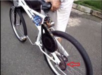
I want build e-bike like this man on youtube http://www.youtube.com/watch?v=9HHhMXwiwTY . Any one know about detail this transmission, like what type freewheel, how that cog mount on freewheel , and is it posibble freewheel mount on the left side?? Please, iam realy interest with this simple desgn i think.
 

Attachments

  • Electric Bike.JPG
    Electric Bike.JPG
    57 KB · Views: 1,448
I don't know, but looks like the bottom cog is just a sprocket mounted to a standard disc brake mount like so http://www.bikeberry.com/engine-kit-parts/view-all-parts/40-tooth-rear-disc-brake-sprocket.html
 
If that is a freewheel, it has to be a left hand threaded freewheel like the ACS Southpaw. It's comparatively easy from a machinist's standpoint to make an 8-hole bolt pattern to engage a 16t freewheel.

Currie Izip bikes used a left hand threaded hub to accomplish a similar purpose.

If it's mounted on a disc rotor interface, then it either has no freewheel or the overrunning clutch is elsewhere in the system.
 
For sure a lefty freewheel set up.
The large drive belt & pulleys are at your local industrial supply house.
You can find lefty hubs around the www.
http://www.staton-inc.com/store/products/Rear_36_Hole_14_gage_Hub_Left_and_right_hand_threads-885-0.html

Mounting the motor is up to your imagination.
 
Better to find a Currie replacement RH/LH hub than that one from Staton. It has irreconcilable design issues, such as tiny axle faces that will damage your frame, and snap ring grooves machined into the axle right at the points of highest stress.

For all the effort Staton put into manufacturing that hub, they should have spent a few more minutes thinking it through.
 
The motor looks like a 63mm diameter RC outrunner. That size would be adequate if it was driving the BB (giving the motor the use of the bikes gears). For this job I would recommend one of the 80mm diameter motors. Common 63mm motor Kv's are from 150-300. The 80-100 can be found as low as a 130-Kv, and the 80-85 is 170-Kv, however...terminating the phases from delta to wye makes life easier on the ESC-controllers, and also lowers the Kv to under 100.

The primary reduction belt looks like one of LightningRods 25mm wide timing belts, way overkill for that particular job, but I understand that the builder may have been unable to find the right pulley diameters in a narrower belt system.

Secondary reduction chain looks like common bicycle chain.

http://www.electricbike.com/diy-mid-drive/
 
I'm not sure about the drive mech. but that is definitely an SE Racing "Big Quadangle" 26" bike, sick!!
 
I'll bet it freewheels at the jack shaft chain-side. Rear sprocket mounted to hub at the disc mount.
The jack shaft assembly looks to be affixed to the rear seat stay.
The motor would just depend on the kv/reduction combo that you want.
I don't really see anything overly complicated
 
r3volved said:
I'll bet it freewheels at the jack shaft chain-side. Rear sprocket mounted to hub at the disc mount.
The jack shaft assembly looks to be affixed to the rear seat stay.
The motor would just depend on the kv/reduction combo that you want.
I don't really see anything overly complicated

Take your 1 minute to look the video....
It is definitively a 63-74 motor at 200kv with a "Staton" style jackshaft assembly, and I bet, an LH/RH hub as Chalo has yet noted....
You can clearly see the freewheeling action at the left side hub level at the end of that video......
 
Back
Top