Small Hi-power bike Concept, reality?

myosis

10 mW
Joined
Jan 18, 2015
Messages
28
Hi,

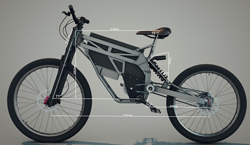
So I've build a concept for a small e bike, I have absolutely no experience in any of this, so i was curios how practical the design actually is.
all%20comp.jpg

frame%20plus%20battery.jpg

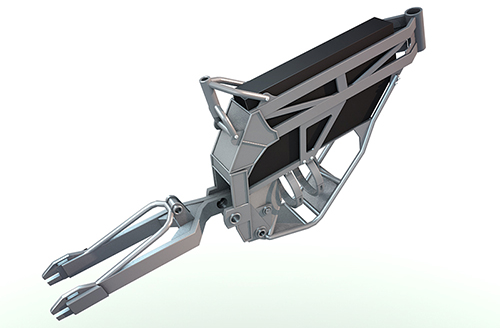
It's mostly modeled after a picture i've seen somewhere. I was however thinking of building it.
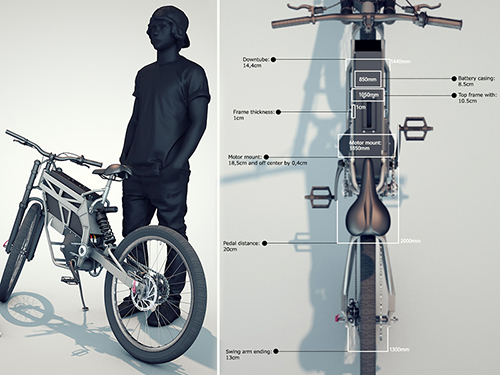
Like, will that custom swing arm work?

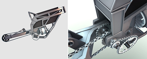
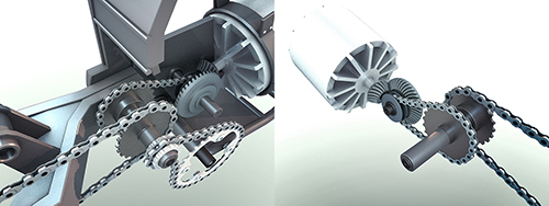
And what about the beveled gears on the motor?, I've never seen anyone do that.
There will be a power loss for sure, I guess..
gear%201.jpg

gear%202.jpg


I have a budget of 3000 euro (excluding the frame).
So here's what I know so far:
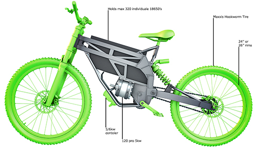
In the battery package fits about 300 (10850) size batteries . if i'm not mistaken that's something like 90v.
I mean if i got the space why not fill it all up. Little downside the battery will weight about 7 kilos...
I know someone how can build it and it would cost 1200 euro
A motor that I think would work nice in conjunction with that would be the; 'rv-120-pro-with-hall-sensors' (400 euros)
I would like to go with ether 24'' or 26'' rims, and like the; 'Maxxis Hookworm' as tires. (100 euros)?

That leaves me with 2300 euros for the rest of the components, is that at all possible?
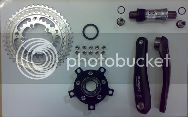
As well as the frame, and gearing setup?

Can't wait to read some responses, good or bad!
Cheers,
Tim
 
Great if you like listening to a super loud worm drive gear whining. Turn the motor and ditch the worm drive. Ebikes with the motor like that have come and gone, for a good reason. Nobody liked that loud gear.

Controller mounted in the stupidest possible place. Put it where it gets air, but not every bit of water, mud, rocks, etc the wheel throws on it. Same location fine if enclosed, but vented properly, but still vulnerable if ridden into deep water. I wouldn't call it design, but I tend to just mount controllers on seat post racks, so they are high, ventilated, and the rack acts like a fender to keep the rear wheel from slinging stuff on it. Design a rear fender on your bike, and then include a controller box into the fender top. Right behind and under the seat.

Otherwise, the frame looks yummy to me.
 
Haha, I was aware of the controller placement. You're definitely right, it needs replacement.
I thought there was a big down side on that worm drive setup, so sound it is...
The reason way i did it was to keep the bike very small, I'm going to rethink the frame a little, but making it pretty wide seams unavoidable, shame, because its really tiny right now.
 
The quality of your renders are great.

You should try to mount your motor so the output shaft is in the same plane as the wheel. The transverse motor mounting you've shown reduces efficiency and increases noise unnecessarily. Harley did that on purpose for their electric motorcycle prototypes just to make extra noise, but most others work hard to find a motor with good efficiency and then don't want to then throw it all away just getting the power to the rear wheel.

Brushless motors come in lots of widths and diameters. You should be able to find something that will physically fit and still meet your power goals.
 
Building a mid drive you start with the advantage of lighter weight, but your design (beautiful) is looking like it will be a wide and heavy frame.

6Kw is not high power on a heavy bike, yet it is enough to wear a drive train pretty quick. Make it light and slick and simple... Tight and stiff, with variable geometry adj points on Dropout and suspension, excentric BB shell and variable headset. It should be stiff to ride, yet flexible to build and tune.
 
Looks good on a first pass.
except...
The transverse motor has been covered. bad idea, lots of reasons.
The controller needs help, but that is the best spot for cooling. Your design has it unprotected and extra close to the front wheel, though.

You didn't give angles on the rendering, but the front end looks like good geometry for low speed street riding. That's fine if your goal is 20mph and rarely riding over a curb. The inclusion of a 5kw motor make me suspect that isn't your intent. :mrgreen:
I think you need more travel and more angle on the front end. Most of the high power, high speed bikes are running 65 degrees or less.

The swing arm has trouble. while the pivot shaft also being the gear shaft is a great design, you need to have it attach to that shaft on both sides. Even if you could build that left side mount stiff enough not to flex and twist, it would be torquing on that shaft in ways that would not be efficient for the gears. Spread that load to both sides, as wide as possible, and you'll better manage the forces. you might even be able to use a hollow shaft to save some weight.
 
As someone who has setup gears like that.. they can be totally silent, but its a real pain in the butt. They have to be designed to be quiet. I dont know everything that goes into it, but I know that means they have to be curved.
Every single transverse engine production car has gearing like this, taking huge loads and moving at high speed. So dont let anyone tell you it cant be done, but realize that unless you find off-the-shelf gearing that is the right ratio and size... its going to be very difficult. Your housing will have to have a way of shimming the pinion depth, and shimming the gear over to get the mesh JUST right.
I would look at the gearing BMW, Moto Guzzi, Honda and other transversely mounted motorcycles use. There may be an "off the shelf" design or setup you could hijack.

also, without any kind of clutch or one way, you will always be spinning the motor, even when you're pedaling at its off. a one way would mean no regen.. so some kind of clutch may be desired... or not. Hub motors dont have this either....it is optional, but something to think about while designing this area.
 
How much total gear reduction do you have there? ~6:1? Is that enough?

Is a hubmotor not suitable for your needs? It would be cheaper, simpler and more reliable, but somewhat heavier. That would free up frame space and allow a much narrower frame.

I like the renderings and general design details very much :)
 
First, your drawings are beautiful! I would not hesitate to hire you to produce CAD renders for a professional product presentation.

I am not concerned as many around here with the efficiency losses of a 90-degree drive, if that choice also allows a major benefit in another area. Successful design is often about balancing several compromises. However, I must agree with dogman on the noise. It is prohibitively expensive to have a custom drive unit produced and have precise bevelled gears case-hardened. This means for you to use a 90-degree reduction, you must find an off-the-shelf unit that already exists.

The existing units are designed and built for industrial applications where the high noise is not an issue. It may be possible to make a new design that runs a little quieter, but again, it would be an expensive custom unit. For your purposes, my first attempt would be a motor shaft in-line with the driven axle, instead of a 90-degree. To be clear, what you have drawn will work, and probably work quite well, but...I am certain you would be disappointed at the high-frequency resonation that the motor and drive unit would send through the frame, and the resulting noise.

I like your battery very much, but I think you would be well-served to work on two designs at the same time. One where the battery stays where it is at, and another where the motor drive is higher, and the battery pack is swung downwards into the downtube area of the frame.

Since the battery pack is a custom shape, and the frame is also a custom shape, you have many options. If you continue with your first design, I will love to see how it turns out, but...since you ask? Here is an E-motorcycle that haunts my dreams. I like how the elevated chain-stay eliminates the need to break a link to change it, or swap-in a chain of a slightly different length. This "prow" location for the battery is one of my personal favorites. I know there are compromises with every choice, but...I think locating a battery right there is worth considering.

 
What are those clamps around the motor? Motor mount?
RV 120 Pro is an outrunner and can't be mounted that way.
It's outer can spins together with shaft.
 
I really like the enthusiasm for the design & renders, thanks. Great tips as well!

I have no experience whatsoever building bikes, or building anything. My profession is in art.
So I have to read all of the suggestions and tips over and take some time to figure this stuff out. (the meaning of some words for example)

However I expected more negative comments, and so far I feel like I can make this work.

When I got the time I'll make a new adjusted frame, and renders with dimensions.
I'm not quit sure what direction i'll go, but we'll see when I start moving some stuff around.

In the mean time any comments are still more than welcome :)
 
Touching back on the right angle drive, If you want to do it just because the idea seems awesome, then you should. But the design you have for it would be a problem, and beveled gears in general have a few problems you'll need to work out.

First, they don't like to work. Beveled gears will convert all the torque you put into them into trying to force themselves apart, and destroying themselves in the process if you let them. They have to be held rigidly in place. That means a very precise and very rigid case to hold them. They also need lube. There is a lot of friction going on between 2 curved gears, they need to stay wet with lube, so you need an enclosed and sealed gear box for them.

the good news is you don't have to reinvent the wheel here. Many riding lawn mowers from the 60s and 70s used a horizontal shaft engine, and needed a right angle drive capable of the kind of power you are looking to use in order to run the belts. Cub-cadet is the first one that comes to mind, but I think Sears Craftsman had some models that used them, too. Or you can go for a new one, like the Peerless 1000 series.
http://www.ebay.com/itm/like/131574267407?ul_noapp=true&chn=ps&lpid=82
http://www.peerlessgear.com/node5380.aspx?nid=300863
http://www.ebay.com/itm/Peerless-10...HP-Tecumseh-/361356542554?hash=item542287425a
 
@silence: So outrunners have a spinning body! Thanks I didn't know that :)

I'm having trouble to find similar motor's like the 'Revolt 120 pro', so I'm going to stick with this one, and just widen the frame.

I made this new setup up and got rid of the 90 deree gearbox. @Drunkskunk: Cool devices those
Right Angle gearboxes!, But sadly I wasn't winning any space with them.

So I've tried something else, but got the idea I made something that 'has again his down sides', or won't work at all:
The motor and the pedal gears are both on the outside of the frame!
E%20bike%20V2-MK3-20.jpg


Now I hoop this works but I didn't even know it how to mount/assemble 'one' freewheel on the outside of a frame, let alone two.
I've seen some pictures of how it looks, but when it comes to putting it all together I am a bit lost, maybe some one here can help me with that.

What are the names of the gears, is there a standard for this setup?
What type /size chain usually goes on this?
En yeah, how does it all go together? (don't be to technical, if that's possible)

So here are the dimensions of the adjust frame:
I'm thinking about changing the 'head angle' to 65 degrees instead of 71, (like you said 'Drunkskunk').

E%20bike%20V2-MK3-19-3.jpg

E%20bike%20V2-MK3-17.jpg

E%20bike%20V2-MK3-21


Most of it is just kinda guessed, so i'm happy to hear any remarks!
Cheers, tim
 
dude... you have some 3d modeling skill. lol.
also, I love how you're keeping the chain drive gear on the swingarm pivot.
 
That looks nice.

I think you'll need a higher reduction ration between the motor and the crank though. A belt may be better for this just for noise. If we know the voltage and kV of the motor, it's easy enough to do the math on gearing.
 
you could buy one of the bikes with the shaft drive and then use a pulley and belt for the gear reduction since they would be coaxial and simple to engineer. there is even a shaft drive two wheel drive bike already manufactured so you could use one of them for assisted 2WD.
 
That's pretty technical. I'm not at home right now, and I'm going to need Google to figure out what's been said about the motor, but in the meantime this is the one I'm planning on using :
http://www.revolt.org.il/rv-120-pro-with-hall-sensors/
And I'm aiming for a 90v battery
 
At 90v, the no-load speed is somewhere around 4000 rpm.
Getting a controller that works well at 90v is a challenge. 72v may be a better compromise.
At that speed, you will need more reduction than what it looks like in the drawings.
 
The Revolt 120 is coming out as a short version very soon I was told so you may not have to widen the frame. 6 to 1 gearing should be just about right to me. KV is 43 x 72v x 26" wheel/tire should put him at about 38 mph unloaded. Myself I'd go 24s 88 volt or 72 volt and 5 to 1.

Looks good to me but I'd drop the battery's down as much as possible so it's not top heavy.

Tom
 
Epic 3D rendering skillz.
your gearing and pivot look good except for the reduction. And you might want to make the primary stage (the chain that actually attaches to the motor) a belt. Belts don't sling their grease when run at high speeds, and run much quieter, too. Belts are also are less likely to slice your leg off if they snap and start whipping around under the power of a 5K motor.

The freewheel issue is easy to solve. There are very few freewheels that will survive 5000 watts. So put the freewheel on the crank. The chain will still be spinning, but the freewheel will only need to lock up for your own pedal power.
ShimanoFreewheelCrank.jpg


As for the motor, there are alternatives Outrunners are cool, but an inrunner is easier to mount in a tight space. Golden motor makes a 5kw motor. here's the tech drawings:
http://www.goldenmotor.com/hubmotors/hubmotor-imgs/HPM5000B Drawing.pdf
trakcni-motor-hpm-5000b-2-7-kw-48v-vzduchem-chlazeny.jpg
 
Capture.jpg

I'm a bit slow sorry, but if I understand it correctly this gear should be bigger?

I really like the sound of using a belt

Correct me if i'm wrong: Reduction is just the difference between gears a higher reduction means smaller to bigger, can i just kind of guess the sizes?
I don't know the proper calculations, I've tried to look it up but i got lost very quickly

A short version of the 120 would be great, and that golden motor looks promising as well!

I was planing on using this controller by the way:
http://www.sabvoton.com/product/sabvoton-new-generation-96v-80a-sine-wave-motor-controller.html#.Vc9J6_mqpBc
 
myosis said:
Reduction is just the difference between gears a higher reduction means smaller to bigger, can i just kind of guess the sizes?
The "ratio" of the reduction stage is the ratio of the number of teeth in each gear.

The maximum pedaling speed for most people is 100 rpm.
Your overdrive from the cranks to the jackshaft is about 1:3 ratio.
So, your maximum jackshaft speed is 300 rpm.
Your reduction from the motor to the jackshaft is about 3:1 ratio.
So, your maximum motor speed is 900 rpm (3*3*100).

The max. continuous power of the Revolt motor is 6Kw at 4000 rpm.
At 900 rpm, it would be 1.35Kw (900/4000*6)

Does that make sense?
 
So here are some of the calculations me and my brother have done, well I've just watched my brother do all the work, but here is what came out:

The wheels on my model have a radius of 30 cm, so the circumference is about 188cm. So within 1 revolution of the wheel, the bike travels 188 cm.
Lets say that at max, I want to go scooter speed with the motor 'around 60 km an hour'
60 km/188 cm = 31915 wheel rotations per hour, or 532 rotations a minute.

So from the engine to the wheel I need a reduction in rpm of 4000:532=7.5
Ok, let's keep that in mind.

Let say I want to pedal along until I hit 20km/h. We can do the same thing as before: 20 km/188 cm = 10500 rph = 175 rpm.
So we want the wheel to get to a max of 175 rpm on pedaling power along. Assuming a person can pedal at a maximum of about 100rpm, we will need a increase in rpm of 175:100=1.75 from pedal to wheel.

If I go with a 3:1 gear ratio on the pedal to jackshaft, the rest of the gear ratios are set. Pedaling, I will go from 100 to 300 rpm first, and so have a ratio of 1.75:3 on the jackshaft to the wheel.

that means that in order to get the 7.5:1 from engine to wheel, we need a gear ratio of around 1:4.4 from engine to jackshaft.


So for example, the gear count could be:
30 on the pedal (A) 10 on the jackshaft (B)
24 on the jackshaft (C) 44 on the wheel (D)
10 on the engine (E) 44 on the jackshaft (F)


For this very particulair set up, he made an excel sheet, where you can play with the numbers,.. because i'm not this smart..
The ratio's will stay the same but by altering the numbers of teeth you can chance the outcomes. very cool stuff!
Link: https://docs.google.com/spreadsheets/d/1mPRKUab3k9TL9nYKmasKulNFRBDGcecerLxveUKjVX0/edit?usp=sharing

Capture2.jpg
 
Back
Top