Miles' Retro-direct gearbox design (schematic)

Miles

100 TW
Joined
Mar 16, 2007
Messages
11,031
Location
London UK
This is a design for a 2 speed retro-direct gearbox.

file.php


An extra gearing stage is added by reversing the rotation direction of the motor.

It wouldn't be difficult to make the gear change automatic - based on motor rpm.

It could be built using chains or synchro belt (one double-sided drive belt needed)
with overrunning clutch bearings or conventional freewheels.

The schematic should be self-explanatory, but please ask if you don't understand it.

Left-click the placeholder image in the PDF to activate the 3D model, then click and drag to rotate.
 

Attachments

  • Retro drive-train.pdf
    281.5 KB · Views: 514
fabulous idea and drawing Miles 8) done with alibre?


Cheers,


D
 
yes i have it already :) just need to practice with it and read the tutorials - beats the hell out of my paint drawings :lol:
 
soz, i thought you meant the 3d pdf creator :oops: .
oh man that is awesome - how long did that take you to put together?
i have a rubbish flat 2d drawing i want to convert?
how cool would it be if you could import pictures and have 3d??
 
now that's what im talking about 8)
can you knock one up for the stinky in the next half hour ;)
very very cool Miles, oh well i got another 8 hours to kill at work i'll see if i can get a circle up :)
 
Miles,

I like that in high gear, where we'd spend most of our time, the gearbox would be at its most efficient operation with only essentially an idler/tensioner and 2 freewheels as additional areas of loss compared to a single direct stage. If these grinder 90° gearboxes didn't have helical gears permitting only 1-way operation, I'd give something very similar a try tomorrow.

3 questions:
1. Don't you have an extra freewheel there on one of small pulleys?
2. Will belts work? My concern is low gear with the load is driven by the back side of the belt. Are there belts that work well with loads on both sides?
3. What do we use for the front freewheels? Will bike type freewheels hold up, or do we really need one-way bearings there?

John
 
Hi John,

Yes, it's effectively switching between a one-stage and a two-stage gear-box. The extra drag from the freewheel/one-way and the idler should be less than the losses from the additional stage.

1.That's not a freewheel on the smaller of the middle pulleys (or the motor one) - if you look closely (you need to download the 3D model), you'll see it's a multi-spline (essentially the pulley is rigid to the shaft) - I just made everything open so that you could see through.

2. I think it would work with belts or chains. You can get belts with teeth on both sides (not cheap, though...) only the Gates and Conti ones truly have equal rating for both sides though, I think.

3. I think you could use freewheels or one-way bearings - it depends entirely on their spec. It makes more sense to use one-way bearings with synchro belts.

Unfortunately, there's no way to have regeneration with this system.
 
Thats just brilliant....Well done Miles, its good to have a true engineer in our midst.

You could definately use Cam-clutch style freewheels in at least the larger pulleys. You just have to keep in mind that their torque rating is lower per cubic volume than a bicycle ratchet/pawl freewheel. the tick-tick-tick sound of regular freewheels does definately get on the nerves so using them would be an added 'luxury'.
 
That drive drawing is beautiful Miles. I've printed it out and stuck it on my noticeboard, next to the tilting trikes :D Seems wherever I look now you're popping up with fresh ideas – are you on holiday right now or just retired to a life of leisure?

Do you have any feel for the maximum power that a system of this type could transmit. I imagine that the weakest link is the freewheels/one-way bearings, but I've no feel for their upper limit. I'm just wondering if this could be applied to a lightweight motorcycle.
 
Hi Malcolm,

I'm self-employed, like you, so.... :)

I think it should scale up fine. You can get whatever spec. you want, for the one-way bearings - a sprag clutch 60mm in dia. should handle up to about 150Nm of torque. Freewheels like the ENO can probably handle more than 250Nm, I would guess.
 
Man I hope chineese spys are reading this so they'll make hubmotors with this type of gearing. Something like low gear to ~10-15km/h with high gear to ~30 would be really sweet.
 
I'm sure you won't have to wait too long before 2 speed geared hub motors start appearing, anyway. There are a few patents for them floating around, now, and it's such an obvious and necessary next step...
 
Certainly.

I was thinking it would be ideal for LH drive to the rear wheel.

For a chain drive, there's always the classic retro-direct set-up - http://www.frankb.us/gears/ - not so compact, though.
 
Miles! That is truly cool as a moose! Now all we need are internal gears that are up to the quality of the freewheels! :(
otherDoc
 
Miles, I'm putting it in this thread because I got the idea from you. Just a minor variation, but this version is "doable" for me. The entire right-side pedal drive is stock. Just found out the GNG motor is reverse-able. So is John in CRs mini-monster.

A recent poster was asking about having a very low gear for off-road, and also a fairly high top-speed for the street. A 3-speed Nexus-as-a-jackshaft might break teeth at 40-MPH power levels. I began trying to remember info from 2-speed discussions. I have been impressed by two builders who ended up using chain and external sprockets for high power. Very robust when using #415 or #219. Since all FWs are straight in-line (unlike BB-drives with one offset chainring), ENO is an option for the FWs.

I've never embraced the classic RD long chain with an idler approach, but I've recently had second thoughts about a RD system using three chains and a jackshaft with 3 freewheels.

RDoneChain.jpg

Most of the reduction is accomplished by the Left-Side-Drive from jackshaft to the rear wheel (which I had avoided due to the classic one-speed LSD), leaving reasonable sprocket sizes for the rest of the drive. Final drive on the left, two side-by-side RD chains on the right from the reverse-able motor to the jackshaft.
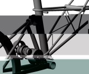
The RED forward-motor gear is pretty simple self-explanatory. If using #25 or #219, the motor-sprocket could be very small and still have at least 11T.

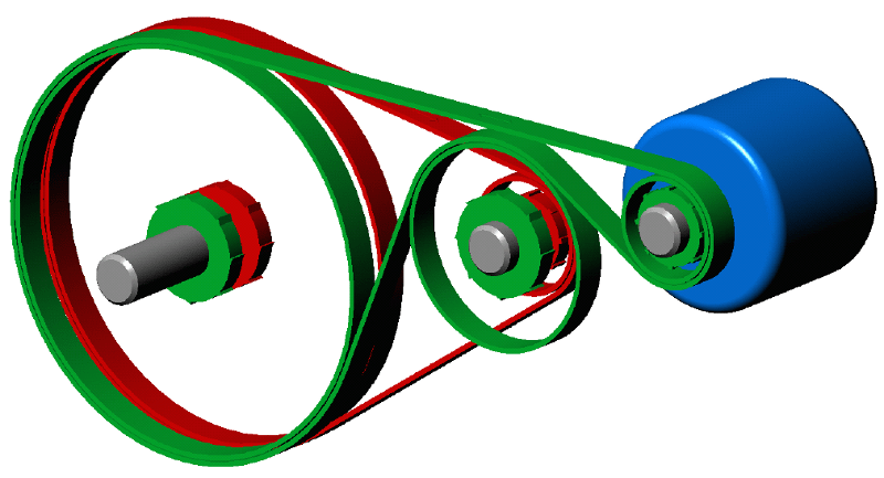
The BLACK reverse-motor jackshaft gear is a Rassy-style with two idlers. I'd spec chain for the reverse-motor gear due to poor belt teeth engagement, but the rest could be belt-optional. Perhaps low gear should be belted so the high-RPMs would be quieter than chain, or the high gear could be belt for the higher tooth-engagement of the motor-pulley?

Anyways here's a graphic of the motor-reverse gear (*goes to get a beer, and then sit down to draw...comes back in a few minutes). Finished drawing, chose LOW gear for forward-motor, and HIGH gear for reverse, but they could easily be the opposite.

RD2chain.png

Enough chain-tooth engagement if I eliminate one of the idlers?

RD2chain2.jpg

Found a sprocket diameter calculator, very easy, type in pitch and tooth-count (bike chain is 1/2" pitch, #219/#25 is 1/4-inch) http://www.rbracing-rsr.com/calcsprocketdiam.html

For a larger 2-speed, that has some room for adjusting the difference between the two gears, a 4:1 as low (64T:16T), and a 2:1 in high (32T:16T). Changing the large sprocket in low will reduce the difference between them, both the 16T are ENO freewheels due to their ability to handle higher power, 16T is their lowest tooth-count. Chain is #415.

In order to make a similar gearbox that is as small as possible, the FWs will be moved to the output shaft. Low is an 11T sprocket to a 22T ENO, and high is a 16T sprocket to a 16T ENO. [2:1 and 1:1]. I don't want to make the drive sprocket for low smaller than 11T, so the 16T in high can be made smaller to bring the ratios closer together. If low is the max 16T:11T, the closest ratios are [2:1 and 1.45:1]

Sprocket diameters in #41 bike chain (because we are using ENO FWs):
11T = 1.77"
16T = 2.56"
22T = 3.51"
32T = 5.10"
64T = 10.19"

The large-range trans would be about 12-inches by 24-inches tall (possibly 4 inches wide). The smaller trans would also be about 4-inches wide, 5 inches front to back, and 9 inches tall.

Edit: since smaller sprockets are louder, it may be beneficial to make the lowest gear be larger sprockets (small idlers)
 
Here's the latest idea.

RD2sp.png

There are three shafts, five sprockets. The center shaft is fixed in position, the upper and lower shafts are adjusted to take up chain slack. The bottom shaft is the power input from the motor (through a toothed belt). Right side is first gear (roughly 2:1 reduction?), and the left side is second gear (maybe 1:1?).

In first gear the central shaft has the freewheel with the lower gear being solid (lower driver gear roughly 13T?). In the left side second gear, the input drive gear has a flanged freewheel (ENO?).

The sprocket on the top left is just a tension idler...

I'm thinking that 219 chain would be best, small links for small adjustments to take up slack, and also stronger than needed so chain strength will not be an issue...Mike (Lightning Rods) has indicated that the smallest chainring that can be made in 219 to fit onto a flanged ENO freewheel is around 23T...
 
spinningmagnets said:
Right side is first gear (roughly 2:1 reduction?), and the left side is second gear (maybe 1:1?).
Hi Ron,

For electric motors, you could argue that, in order to justify a transmission stage/step (and the inherent losses) it should make some torque/speed change in absolute terms. Obviously, you need to except cases where there are no, or very minimal losses (eg. middle gear on the classic 3 speed IGH).

So, it might be better to have a larger step than 2:1 in the lower gear, in order to have a greater than 1:1 ratio in the higher gear (still keeping the 2:1 difference between ratios)?

Perhaps your are constrained by the 23t #219 sprocket though?
 
I only wanted to make a working prototype to show that this idea is worth considering, and is not horribly difficult to actually make. I am open to using any gear ratio that experienced minds feel would be desirable (and of course, could be achieved with actual off-the-shelf parts). Increasing the first gear ratio even more shouldn't be a problem.
 
looking at the very first post, it mentions that having the controller automatically reverse direction is easy...
I've though about this, well how would you structure the algorithm for this ? Lets say rpm forward is positive, rpm reverse is negative (so +500rpm and -200 rpm etc etc)
then what would the flow diagram look like for the automatic reversal ?
 
Back
Top