A thru-the-gears serial drive- KISS, COTS, No FW cranks!

Qwiksand

100 W
Joined
Nov 10, 2009
Messages
160
Location
Bowie, MD
KISS- Keep it simple, stupid (though there are two more chains than a standard bike, the motor speed reduction/pedal speed multiplication mechanism is dead simple)
COTS- Commercially-available, off the shelf parts (mostly :wink: )
No Free-wheeling cranks necessary- pedal input freewheeling happens on the jack shaft

A little background:

I built this prototype up using my trusty old 2004 Kona Stinky frame last fall and have put about 400 miles on this set-up. It uses a LightningRods lower BB/motor mount and his 1500 watt rated motor which meets pedal input at a jack shaft mounted on the seat post. I'll show each of these parts in detail as this thread progresses, but here's a couple pics to show the system.
kona motor side.jpg

kona pedal side.jpg

Bike w/drive system weighs in at 51.5 pounds and the battery as shown (9s2p or 18s1p of saggy, four year old Zippy 8000mah cells) weighs 8.8 pounds- total system weight at 60.3 pounds. When running 9s, this makes for an efficient pedal-assisted cruiser which will cruise along in the low 30's with significant pedal input or putz along at 25mph with minimal to moderate human assistance.

When I put the series plug on the battery pack, the bike becomes much more fun pulling 3kw peaks. Here're a couple pics of yesterday's top speed run. Full disclsoure: this was accomplished on a very slight downhill section of roadway with a 10-12mph tail wind. But still, 55mph indicated on cycleanalyst (53mph on GPS) with batteries sagging to 63 volts is not too shabby!
Max_speed.jpg
Max speed GPS.jpg

View attachment 11

There is a major down side to placing a jack shaft which drives the rear wheel on the seat post of a full-suspension bike and that is MAJOR TORQUE INDUCED SUSPENSION SQUAT!!

Which is why I'll be transferring this proven drive system onto a hard tail frame I've got laying around. With this thread, I hope to fully document this process.

The new build:

The recipient frame is an old (year unkown) Fetish Obsession dirt jump frame with horizontal track-ends. I've got some battery mounting hardware already made for this bike from it's previous life as my "hood cruiser" hub motor set-up.
fet ob frame.jpg

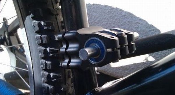
The jack shaft consists of a 40mm 1 1/8", 31.8mm stem, 1/2" shaft, 1/2" id x 1 1/8" od bearings and threaded free-wheel adapters available from staton-inc. The stem as a jack shaft mount idea comes from a post I saw somewhere on this site a while back, I'll post a link when I find it as the OP's idea was very clever and saves me some fab time! *Edit* All credit for the stem/jack shaft goes to gwhy!- here's the post: https://endless-sphere.com/forums/viewtopic.php?f=28&t=22245&start=0 (special thanks to spinningmagnets for the reference/link).
jackshaft parts.jpg

I'll show the freewheel adapters in more detail when I mount their respective freewheels and sprockets. To clear the narrow bb (113mm) I'm using, the pedal side of the jack shaft needed to be drilled/tapped for a retaining washer which will fit into the recessed 13t BMX sprocket.

Drilled
drill shaft.jpg

Tapped
tap shaft.jpg

Here's the jack shaft mocked-up
JS side.jpg

JS close.jpg
 
Nice work! The space right behind the seat-tube has always called to me as a perfect location for a jackshaft. It doesn't eat up any space where a controller or batteries could go so its like finding free real estate. Glad to see it work for someone. I ended up giving up on mine due to the massive chain length change under suspension travel. The list of custom parts and chain tensioners took it far from COTS theory. Hearing about the suspension squat makes me feel a little better about giving up on that.

Hardtail should be a fun ride and plenty stout being a dirt jump frame. It will probably feel pretty snappy without the suspension soaking up the thrust. Kinda sad to see it all taken apart after all that trouble to get it packaged on the Kona but if it rides all wacky then its totally understandable. The Kona would make a nice high powered hub bike with all that room in the triangle for batteries. Still a nice bike to have laying around.

Good luck.
 
Regarding the suspension squat:

When I first swung a leg over the new set-up, I felt it was unrideable. The rear would squat and the front would come up with zero effort, but after a bit of time it's amazing what you get used to. Now, I just roll the throttle to settle the rear and then apply more go-button as necessary.

As to the Kona, don't shed any tears- she's not retiring, just getting a new power system. It'll be a variation on this system, but using RC motor(s) and a Jackshaft that will be positioned just in front of the BB. But that's a project for another day...
 
I stripped the stinky down, ready to transfer drive and forks/bars/controls over to the hard tail.
strippedstinky.jpg

A little closer look at the motor and mounting plates. I got these from Mike over at http://www.lightningrodev.com/parts/index.html. These lower mounting brackets are one of his first versions; I believe he has since revised the lower mounts, but they should still work as I'm not using the adjustable part of this system. The aluminum flat stock/pulley/spring thing in the pic is an improvised tensioner- it works, but it's noisy and will soon be replaced.

motorfront.jpg

motorback.jpg

Since I'm not using these lowers to tension any part of the drive system, I replaced the fiddly bolts with some shorter/stouter variants.

motorplates.jpg

The first stage of this drive system reduction is approx 5.7:1 using #25 chain. There's a 14t driver sprocket on the motor (I think I bored a 3/8" http://www.surpluscenter.com/Power-Transmission/Sprockets/Finished-Bore-Sprockets/14T-3-8-BORE-25P-SPROCKET-1-2742-14-C.axd sprocket out to 12mm to fit the motor shaft) and a 80t driven sprocket from http://www.staton-inc.com/store/index.php?p=product&id=1752. I welded the driven sprocket to a 16t freewheel to simplify mounting, but this particular sprocket is designed to fit on one the 5-hole BB freewheels like this one http://www.staton-inc.com/store/index.php?p=product&id=2070.

25_80t.jpg

In the upper left corner of the above picture is a 1/2" ID freewheel adapter, found here: http://www.staton-inc.com/store/index.php?p=product&id=1930. The 80t sprocket/freewheel is threaded on to this adapter and then attached to the left side portion of the jackshaft spindle.

Here's a couple pics of the motor/plates mounted to the hard tail frame.

motormountedfront.jpg

motormountedrear.jpg

That's about as far as I got this last weekend. I ran into a snag, I couldn't find my ACS crossfire freewheel remover tool so I had to order another one. The pedal input is a 48t crank/chainring driving a 13t ACS BMX freewheel. The 13t ACS freewheel threads on to a 30mm x 1.0 threaded freewheel adapter found here: http://www.staton-inc.com/store/index.php?p=product&id=2013
 
This is my series/parallel plug set-up. Covers are printed in blue PETG from eSun and the outer tube is a standard 3 x 4" PVC gutter downspout. The two printed endcaps are held in place with a 1/4" threaded rod and one barrel nut on either end. The DB25 connector handles the balance taps.

No flash

View attachment 1

With flash to show the translucence of the blue PETG, this stuff prints beautifully.

flash.jpg
 
Thanks for posting this. The results show you are a very handy builder...

I think it was UK builder "gwhy" that posted using a BMX handlebar stem as a jackshaft mount several years ago. I always thought it was clever, and I haven't had an opportunity so far where that would have worked for the project...

JackshaftGwhy.jpg
 
Spinningmagnets turned me on to your build. Very nice work! I had an LOL moment when you said that you were switching over to a hard tail because that was my main reservation about the original design. We have to keep the chainline in line with the swingarm pivot or all kinds of hell ensues. The "crossbreak" location in front of the BB is about the only space available on a commercially produced FS bike. Ideally we'd want the jackshaft located right on the swingarm pivot like the Motoped frame.

Initially almost all mid drives went through the bottom bracket because it's easy to lay out. It's just flat out stupid to reduce the motor to 30x just to be able to run it through the BB and then overdrive it again to the rear wheel. You were absolutely right to try to avoid doing this. You found out right away that it's not so easy to do, especially with full suspension bikes.

I'm looking forward to seeing what you do next. You have the right kind of brain for this mid drive puzzle. Stay with it.
 
fechter said:
Nice!

Any idea what kind of motor that is (like who makes it)?

These are Chinese electric rickshaw motors. I import them to the US from the factory in Shanghai. You can also get them from GNG in China. A number of motor factories in China make this same design. Some are better quality than others.
 
spinningmagnets said:
I think it was UK builder "gwhy" that posted using a BMX handlebar stem as a jackshaft mount several years ago[/img]

Awesome, thanks for that link! I've edited my first post to give credit where credit is due.

LightningRods said:
The "crossbreak" location in front of the BB is about the only space available on a commercially produced FS bike.

I agree completely and this is the direction I'm headed with a prototype 2-speed set-up. Without spoiling the whole unveil, here's a link to whet appetites: http://www.vexrobotics.com/217-3290.html
 
Got the ACS tool and removed the 13t freewheel and , with a little heat, also removed the 16t track cog from its old adapter. This set-up on the kona was using a 5/8" keyed shaft, but I was only able to source 1/2" ID bearings with an OD of 1 1/8". The 1/2" shaft looks a little puny in comparison to the 5/8", but time will tell if it'll hold up.

Here's the pedal side of the jack shaft sprocket and adapter arrangement- this is how they align on the shaft itself. With this orientation, the 16t track cog driver sprocket and the 13t bmx freewheel tighten against each other when under leg and motor power- they are not able to loosen due to the freewheels.
sprockets_adapters.jpg

Pedal input to the jack shaft is multiplied 48t/13t for a ratio of approx 3.7:1. The rear wheel is then driven by a 16t track cog threaded onto a freewheel adapter from staton-inc. The rear cassette of the bicycle is where the 2nd stage of the motor reduction takes place. I've been running with 7 gears (on a 9 gear cluster with the 11t and 13t locked out) with the lowest being a 34t and the highest 14t. This gives a transmission spread of approx 2.4x.
View attachment 1

With this jack shaft set-up, chain line is adjustable and I think I center over the 23t sprocket. I'll list out the sprockets I'm running when I set-up the rear wheel, it's a modified cluster.
pedal_JS.jpg

Here're a couple shots of the motor side reduction (again, that aluminum tensioner is on the short list to be modified). I still need to lop off the excess shaft, but I want to make sure I've got the chain aligned properly before committing.
motor_side.jpg

motor_side_angle.jpg
 
I only let you go forward with that build if you promise that you will install some kind of guard before taking it for a test ride. That big sprocket next to your leg can do some major damage. :twisted: :twisted: :twisted:
 
Ecyclist said:
I only let you go forward with that build if you promise that you will install some kind of guard before taking it for a test ride. That big sprocket next to your leg can do some major damage. :twisted: :twisted: :twisted:


The danger of being mauled by the mechanism is part of the allure 8)

This set-up only likes to eat pant legs on the motor drive side and those little #25 sprocket teeth aren't near as nasty as standard bicycle 1/2" pitch. I mostly ride in shorts though, I'll promise to keep my leg hairs trimmed :)
 
Qwiksand said:
Ecyclist said:
I only let you go forward with that build if you promise that you will install some kind of guard before taking it for a test ride. That big sprocket next to your leg can do some major damage. :twisted: :twisted: :twisted:


The danger of being mauled by the mechanism is part of the allure 8)

This set-up only likes to eat pant legs on the motor drive side and those little #25 sprocket teeth aren't near as nasty as standard bicycle 1/2" pitch. I mostly ride in shorts though, I'll promise to keep my leg hairs trimmed :)

In that case enjoy it.
BTW: It is a cool project and I'm looking forward to your next post.
 
If you are running a rear derailleur and a rear cluster, how is the chain routing back to the jackshaft? Doesn't look too much closer to the rear compared to the bottom bracket but definitely high enough for the chainstay to be in the way. Looks like some good progress.
 
There's going to be some serious twisting forces on the clamp that holds the jackshaft. Is there a way to key it to the frame so it can't twist?
 
Qwiksand said:
I agree completely and this is the direction I'm headed with a prototype 2-speed set-up. Without spoiling the whole unveil, here's a link to whet appetites: http://www.vexrobotics.com/217-3290.html
"Page Not Found"....

Edit:
If you're outside U.S. you have to select "United States" on their website and then click the above link, or you "get Page Not Found"....
This shows the "magic" bit: http://www.vexrobotics.com/vexpro/motion/gearboxes/3cimballshifter/217-4098.html :)
 
Ecyclist said:
So, with this type of gear box you will be cranking two sets of sprockets, one engaged and one free?
Miles said:
Qwiksand said:
I agree completely and this is the direction I'm headed with a prototype 2-speed set-up. Without spoiling the whole unveil, here's a link to whet appetites: http://www.vexrobotics.com/217-3290.html
"Page Not Found"....

Edit:
If you're outside U.S. you have to select "United States" on their website and then click the above link, or you "get Page Not Found"....
This shows the "magic" bit: http://www.vexrobotics.com/vexpro/motion/gearboxes/3cimballshifter/217-4098.html :)

I've started a new thread for the ball shifter project: https://endless-sphere.com/forums/viewtopic.php?f=28&t=79555
 
DanGT86 said:
If you are running a rear derailleur and a rear cluster, how is the chain routing back to the jackshaft? Doesn't look too much closer to the rear compared to the bottom bracket but definitely high enough for the chainstay to be in the way. Looks like some good progress.

Final drive comes off the 16t track cog and routes between the tire and the chain stay.
final redux side.jpg

You were very keen to note that there is not a lot of clearance for this, made even worse by the "S" bend chainstays on this frame. The kona has straight shot chainstays and the drive side is even lowered a bit, so this was less of a problem.
final redux angle.jpg

I plan to remedy this by running a chain guide right where you see the nut-driver in the pic below. This will coax the slack side of the chain to avoid the narrowest portion of the chainstay, but should be far enough forward to allow enough chain twist for the rear derailleur to still be able to function. Added benefit of using a hardtail, I can mount the guide directly to the chainstay.
guide needed.jpg

fechter said:
There's going to be some serious twisting forces on the clamp that holds the jackshaft. Is there a way to key it to the frame so it can't twist?
boisrondevens said:
fechter said:
There's going to be some serious twisting forces on the clamp that holds the jackshaft. Is there a way to key it to the frame so it can't twist?


Cool concept but you have to find a way to avoid the jackshaft to twisting...

I had no problem using this bracket on the kona and it had to cope with the additional strain of the moving swingarm.
old JS housing.jpg

I'm hoping (wish in one hand, sh!t in the other right? :D ) the stem will clamp with sufficient force- yet to be tested. Pinning to the seat tube is an option, but I'd be more likely to add braces/torque struts to limit twist. I'll let you all know how it goes.
 
Back
Top