MY1018 Mid-Drive Crank Freewheel Hill Climb Assist eMTB Proj

Joined
Oct 11, 2016
Messages
109
Location
SoCal USA
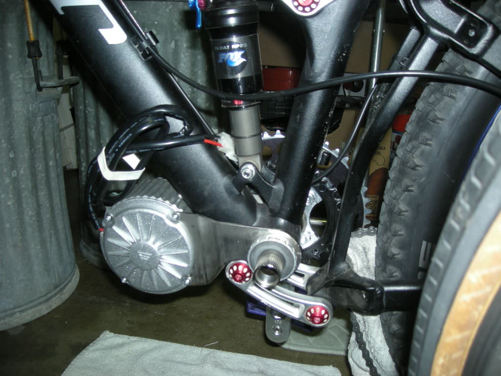
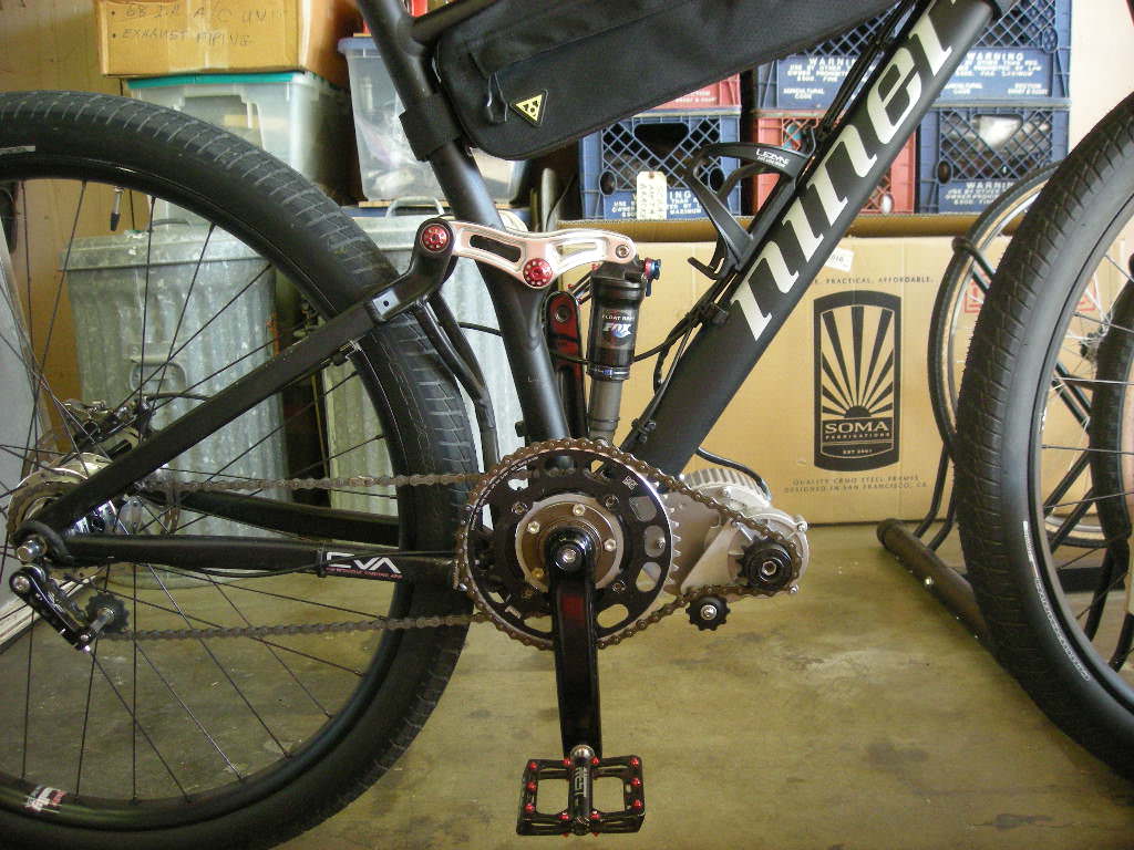
In an effort to give my aging lungs a boost when climbing hills off-road, I have decided to embark on a light weight mid-drive project that will solely be used when climbing hills when I’m out of lungs or legs. The electric motor, battery and other related essentials will be additional dead weight on the bike until needed, thus the system must pedal with the least drag possible from all the E-assist farkles. I believe the best way to achieve this is to use a crank arm freewheel sprocket up to a small geared motor (also with a freewheel sprocket) within the frame triangle.

The motor I have selected is an old school brushed MY1018 450W 24V that is stated to be able to run 36V without issues. It is the smallest and lightest geared motor I could find that seemed to meet my needs. The one I purchased is said to be rated for 25A as well, but I am not sure it will run reliably at higher than 18-20A. As I understand it, this motor is normally run at 15A on old Currie eZip Trailz electric bikes (in a slightly different build form), but each buyers build specifications can be unique. It is not clear if this motor is produced differently to achieve its’ stated 25A rating (?).

I picked up this motor with various rear stay mounting parts and a YK31C controller. I also have a left side under bar thumb throttle left over from a prior project. This is my first custom build, so please bear with me if some of my questions seem trivial to the electrically experienced.


Here are the motor and controller stated specifications:

MY1018 - 24V 450W GEAR REDUCTION “BRUSH” MOTOR
(Came with rear stay mounting bracket, sprocket, chain, nuts & bolts)

Specs:
- 24 Volt, 25A Rated Load, 2.5A No Load
- 1.43Nm at the output sprocket @440 RPM
- 12 gauge power leads
- Reduction Ratio: 9.78:1
- 9 tooth sprocket for 1/2'' x 1/8'' pitch standard bike chain
- Direct Drive (No Free Spooling)
- Alloy case for good heat dispersion.
- Bicycle style mounting bracket Included. (Suits the 250w and 450w models)
- Suitable for Forward and Reverse Operations
- Weight: 2.2KG / 4.85LB (alloy motor and frame!)


YIYUN TECH - YK31C
(Brush motor controller for electric bicycle & scooter)

Rated voltage: DC 36V
Current limit: 28A
Rated power: 500W
Matching motor: DC brushed motor
Under Voltage Protection: 31.5V

Wire Interface Definitions
Battery: Thick Black (Power Negative) / Thick Red (Power Positive)
Motor: Thick Yellow (Motor Negative) / Thick Blue (Motor Positive)
Ignition Switch: Thin Red (VCC) / Thin Blue
Indicator: Thin Red (Indicator power output) / Thin black (Indicator Negative)
Brake: Thin Yellow (Brake signal) / Thin Black (Negative Power)
Speed governor: Thin Blue (Speed handlebar Signal input) / Thin Black (Negative Power) / Thin Red (5V Positive Power)
Charge Port: Thin Red (charge input power Positive) / Thin Black (Power Negative)
Brake Light: Thin Red (power Positive) / Thin Black (Power negative)


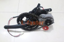
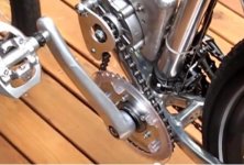
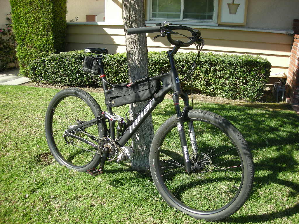
Initially I will be installing this mid-drive in my Soma B-Side V.2 Belt Drive custom build to test it and work all the bugs out, but plan to eventually move this to my full suspension MTB for climbing off-road hills only. Low speed torque is the application for a 230lb. rider.

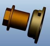
The setup will be similar to the kit offering pictured below, but the motor will end up mounted within the frame triangle (not in front of the bottom bracket and below the down tube), because the full suspension MTB can’t accommodate a motor there.

If any experienced builders can chime in with their thoughts and hands-on knowledge regarding the basic setup idea, including any problems they see and/or possible best further motor gearing reduction through the motor to crank sprockets for ideal climbing cadence, please do.
 

Attachments

  • FreeWheelSprocketOnMotorWithCrank.jpg
    FreeWheelSprocketOnMotorWithCrank.jpg
    39.3 KB · Views: 8,803
The picture below is an in frame triangle application of a MY1018 with left side drive.

This is the motor location I will use, but haven't decided on left or right side drive. I can use a normal right side freewheel on the left side with the motor in front of the BB, but that setup will always turn the pedals when under power; although this will likely provide the least drag when not under power. One problem worth noting with left side sprockets is rear frame stay clearance issues.

A single freewheel on the motor driving a fixed sprocket on the right side will also require the pedals to move when under power, but in addition will require the crank to motor chain to be turned when pedalling without power. My guess is this will have slightly more drag, but is the easiest application because you can simply use a standard double or triple front sprocket pedal assembly.

Only the kit setup pictured in the prior post with a freewheel on the crank and motor will allow power without pedalling, but also requires the crank to motor chain to be turned when pedalling without power; so there's that little bit of additional drag once again.

Hopefully I have those three paragraphs correct with respect to logic and freewheel crank arm righthand threads. Turning freewheels in my mind gets confusing at times and I don't want a jack shaft setup.

Question: Do dual flange bolt hole freewheels exist?
Does a freewheel exist with bolt hole flanges on both sides (one flange attached to the inside and the other flange attached to the outside), that can be bolted to the outside of a right side sprocket that is already on a standard pedal assembly, and then have an additional sprocket bolted to the other flange, thus creating a freewheel crank only for the chain sprocket that goes up to the motor, while the pedal to rear cassette sprocket remains fixed to the crank?
 

Attachments

  • MY1018InFrameLeftCrankFreewheel.jpg
    MY1018InFrameLeftCrankFreewheel.jpg
    28 KB · Views: 8,686
This is the small space within the frame triangle that I have to work with. Picture is of an actual to scale cardboard cutout with scale motor photocopy.
 

Attachments

  • DSCN1503.JPG
    DSCN1503.JPG
    132.5 KB · Views: 6,465
The more I think about how I plan to use this bike (90% pedal) and motor (10% power assist when climbing), the more I think a simple right freewheel crank arm mounted on the left side, with a 36ish sprocket and fixed 9T at the motor will be the best setup. Basically similar to the picture two posts prior.

Currently the bike has a Race Face Aeffect SL Cinch crankset with 24mm spindle. Possibly by using a slightly longer spindle so a Tri-All ISIS type right side freewheel crank arm can be installed on the left side, it'd simple be a bolt together project (?).

Does anyone know how the left crank arm on the Race Face crankset above is attached to the spindle? Is it even removable? Threaded on? Press fit? Welded?

I can't find a source for 24mm spindles by length. I do see Race Face makes a couple different sizes in the 30mm.

Does anyone have a source for 24mm ISIS on both ends raw spindles?
 
honestly, for a 90% pedal, only helper when needed low power setup... I would want to keep it much simpler.

a tiny geared hub motor, tiny lipo pack and a cadence sensor with a button throttle (push for WOT)

If you like it but dont like the cadence sensor, swap out the bottom bracket for a torque sensing one.. then dial the power to match and it will be just like pedaling, only easier for every speed.
 
MrDude - You've got to be kidding. A small geared "hub" motor on a 29er FS MTB really isn't a good match for off-road hill climbing at all. You don't want that weight up front or in the rear. That motor trying to spin a 29" wheel at ~6-8mph is just going to burn up.
 
First. I'm sorry, I would not be offensive at all.
My concerns about that system and a Carbon FS frame are primarily about the way it will be mounted, a carbon frame couldn't be clamped as a normal steel frame, second, about aesthetics and overall efficiency .
I think is not that strange to say that a geared, non freewheeling brushed system typical for cheap bikes, small mopeds minibike and miniscooter is not the best fit on a FS carbon frame... :wink:
I will be cuorious, also, to see the entire drive weight, with all the parts included (primary chain, sprockets, freewheels, final mounts and controller etc.) for a better comparison with other systems.

- 1.43Nm at the output sprocket @440 RPM
SUre about that?

Santa'sLittleHelper said:
This is the motor location I will use, but haven't decided on left or right side drive. I can use a normal right side freewheel on the left side with the motor in front of the BB, but that setup will always turn the pedals when under power; although this will likely provide the least drag when not under power. One problem worth noting with left side sprockets is rear frame stay clearance issues.

A single freewheel on the motor driving a fixed sprocket on the right side will also require the pedals to move when under power, but in addition will require the crank to motor chain to be turned when pedalling without power. My guess is this will have slightly more drag, but is the easiest application because you can simply use a standard double or triple front sprocket pedal assembly.

Only the kit setup pictured in the prior post with a freewheel on the crank and motor will allow power without pedalling, but also requires the crank to motor chain to be turned when pedalling without power; so there's that little bit of additional drag once again.
confusing.... :?: If you use a RH freewheel on the motor output mounted LH it will work but you will have the input chain at the crank always turning.

You simply need a LH freewheel at the motor output IMHO, like most crankdrive systems have, but a 9t #410 (if thats what you need) freewheel is an hard find....Sure someone makes a roller or sprag one-way bearing assembly with #410 sprockets, but will be not cheap and not easy to find I guess.

Santa'sLittleHelper said:
Question: Do dual flange bolt hole freewheels exist?
Does a freewheel exist with bolt hole flanges on both sides (one flange attached to the inside and the other flange attached to the outside), that can be bolted to the outside of a right side sprocket that is already on a standard pedal assembly, and then have an additional sprocket bolted to the other flange, thus creating a freewheel crank only for the chain sprocket that goes up to the motor, while the pedal to rear cassette sprocket remains fixed to the crank?

In A RH crankset that has fixed output and freewheling input (LH or flipped RH unit) both with big diameters, I think will be hard to match the pedal cadence with the motor rpm, It could result unsafe and inefficient in some situations, plus you'll probably have to deal again with improper chainlines. A cheap try could be a flipped RH flanged freewhel and a adapter for 6 bolt cogs to bolt-on a fixed output sprocket
mv_disc_adapter.jpg

That TryAll spider could be also a good base, if you are creative and have enough tools to adapt it to your needs.... :wink:
L_5armspider.jpg


EDIT: maybe that spider (or even the 6 bolt adapter) could be flattened at the visible side till the level of the chainring mount , except for the threaded "stub" than you could flat out that stub to the thread thickness that allows you to mount it with a RH freewheel unit on the same threaded crankarm (RH).
A useful option IMHO should be to grind, file or whatever, that cyclinder to create the right prongs count and shape for the flanged freewheel unit of your choice, this would save some mm of space for the assembly (ACS and Dicta have the threads passing thru the entire inner diameter so are suited to be flipped) and bond the freewheel and the adapter together. you than need to bond everything to the crank threads too, because in fact the fixed part tend to screw on the assembly while the power input tend to unscrew it, hopefully the bond action and the balance with the crew-unscrew forces willl sort out with a stable assembly. Having the spider or adapter for the fixed chainring engaged with the freewheel prongs, allows you even to use that fixed flange as removal tool if that will be eventually needed. If you mount the fixed sprocket after the freewheel the prong engagement will be not possible anymore, but the fixed sprocket will act as a lockring to prevent the unscrewing of the flanged freewheel....
Note that With this setup, also, when you pedal backward, you run the entire primary+gearbox+rotor line while not under power, and you are obviously not allowed to pedal back at all if the power is on....
 
"First. I'm sorry, I would not be offensive at all..."

I haven't taken offense and I hope others haven't either (?).

Much of what you point out is just what I went through when selecting this ~5lb+ small geared motor over a 100mm wide front hub motor. First and foremost are the small size, narrow width and ability to run either direction (my research indicated that only one suitable hub motor can run in reverse and that requires internal work, plus dealing with wiring going through the axle). The design of the MY1018 makes mounting it very easy. Mounting is planned to be from the bottom bracket just like many under the bottom tube motors, only this motor will be inside the frame up out of the way of obstacles. The two composite or aluminum plates will have a connecting bracket that comes down from each side and across to the other side that will attached to the bottle mounts. This will simply add torque support and the weight will be downward against those attachment points. Simple clean "H" setup with BB at the bottom of the “H”, motor at the top of the “H” and the cross dash attached to the bottle mounts.

Just with that mount and a 12-13T freewheel on the motor with a right side chain to the outside 104BCD on a dual sprocket crankset and I'm in business for about $150-$200 less battery. :mrgreen:

Yes, without a freewheel at the crank I will have to pull the chain when not under power, but I can use this setup to test the application and gearing. I don't see the crank being required to turn as an issue for how it will be used; only under power during difficult climbs when in the low gears (30T X 28-32-36-42T currently). Remember this isn't meant to be a MTB electric motorcycle like most builds here (not that there is anything wrong with them, it's just not what I'm looking for). I'm a trail MTB rider simply looking for added assist on climbs only.

After testing with a right side motor drive I can consider a whole new wider crankset with something like a Tri-All freewheel arm on the left and flip the motor. In this configuration the fixed 9T sprocket can go back on the motor and a smaller crank sprocket to achieve the same gear ratio, plus require less added width the BB spindle because of the smaller sprocket.

The key elements to keep in mind for this build are that it will be pedaled 90% of the time WITHOUT power (crank freewheel probably best) and it must be light weight.
 
I’m not too sure about how accurate posted specifications are on the web. Here are a variety of specifications for the MY1018 from a builder source that seems to outline its’ many different configuration abilities. One thing I did note is the reduction of Amps on the 450W 24V version from 24A to 16A when running it at 36V.

Electric bicycle hub motor MY1018
1)Small , less weight
2)High efficiency, easy adjustment of speed

Specification: 250W,350W,450W
Voltage: 24V, 36V
Reduction ratio: 7.18:1
Rotation: 3000-4000rpm
Torque: 0.80-1.43 N.m
Efficiency(%): ≥78

Specifications and Product Details:
Model MY1018
Specification----------250W 24V/36V-----350W 24V/36V-----450W 24V/36V
unload current/A-----≤2.5------------------≤2.2-----------------≤2.5/2.2
unloaded speed/rpm-3150-----------------3550-----------------4000
rated torque/N•m----0.80-----------------1.11------------------1.43
rated speed/rpm------2750----------------3000------------------3000
rated current/A-------≤13.4----------------≤8.7-----------------≤24.0/16.0
efficiency/%-----------≥78-------------------≥78------------------≥78
Reduction ratio 7.18:1
Application Electric Bicycle

Advantage and Features:
1 long life and maintenance-free
2 Small and mini, less weight
2 excellent start performance and high efficiency
3 More economical
4 Adopt Norm Planetary deceleration system,oil-impregnated gear and special modification nylon gear to increase resistance to wear of the gear.
5 Modified nylon gear can withstand worse temperature to ensure that the gear can work normally in any temperature environment,
6 High efficiency and wide platform, quick starting and strong capability for uphill.
7 Popular in European and American market.

Specification

Voltage:24VDC
Rotation:CW
No load: No=470rpm±10% Io=1.5 A REF
Load:T=10.85N.m Nn=395rpm±10% In=26.0 A max
Lead wire:12AWG Black- Red+ 860±30mm Long
With pitch to 12.7mm, roller diameter of 7.8mm, 9 teeth sprocket
Motor diameter 111mm, length 90mm,
Linked side installation, comes with heat shield outside electric bicycle motor with built-in gear reduction transmission. Gear ratio: 79:11 (7.182).
Motor speed: 2750RPM. Output shaft speed: 382RPM. Includes 9 tooth sprocket for 1/2" x 1/8" bicycle chain.
Powerful four brush permanent magnet electric motor design. 100% ball bearing construction. 24" long power leads. Shaft rotation reversible by reversing power leads. Three bolts
on front side of motor for mounting.
Motor dimensions: 4-1/4" outside diameter x 23/4" long excluding transmission and output shaft, 4-1/2" long including transmission and output shaft.

Attached is a picture of the actual motor received.
STICKER ON MOTOR STATES (C6453582):
CE MODEL: MY1018-1
Voltage: 24V
Power: 450W
Speed: 420rpm
Current: 25A
 
As received, this motor is designed to attach at the left side frame stay and power a left side freewheel at the rear hub. Sprockets provided are 9T fixed at motor and 16T freewheel at rear hub. My research inidcates that on a typical 26" rear wheel bicycle it peaks out per this article at:

https://www.electricbike.com/2014-ezip-trailz-lithium/

MY1018 @ 24V
9Tx16T = ~20mph
9Tx20T = ~16mph
9Tx27T = ~11mph

MY1018 @ 36V
9Tx27T = ~16mph

That information is very useful in calculating how it might work setup like I plan to do it. This is a very well known motor that has been in use for many years and has gone through a few changes over those years. There are many builds here from years ago that use this motor. The current versions are said to be quieter than the old straight cut gear models (we will see?). Even if this exercise turns out to be a total bust, I'm only out less than $100.

But the experience in doing it and more importantly the experience riding my nice FS MTB with that extra weight is invaluable in determining if an eMTB can "feel right" pedaling without power at all.
 
Does anyone know where I can purchase a 12T freewheel sprocket for a MY1018 11mm bore 4mm keyway or an adapter that will take a 12T 18mm freewheel in the USA?

I have only found 1 international seller and they want just about as much to ship it as the item itself; about $18 shipping!

Thanks for your help.

I can't find any 12T 11mm bore 4mm keyway freewheels anywhere period. Here's what the adapter looks like for the 12T 18mm freewheel:
 

Attachments

  • Adapter11mmBoreAccepts18mm12TFreehweel.jpg
    Adapter11mmBoreAccepts18mm12TFreehweel.jpg
    14.6 KB · Views: 8,425
I came across this interesting kit today while looking for videos of the 2017 Focus Jam 2 Pro 29er I have my eye on.

The LIFT-MTB kit appears to be a MY1018 with a very unique mounting bracket and chain guard and tensioner:

315em93.jpg

https://www.lift-mtb.com/

So far I loaded a Race Face dual chainring mount with a 30T and 44T ChopSaw on the 104BCD mount, but the ChopSaw is on the outside of the bracket and clears the swingarm.

2a4o9pc.jpg


Been racking my brain on the best way to configure the mounting bracket to put the motor in the triangle...

29dzk7c.jpg
 
Hmmm… Very interesting kit. 33lb bike and motor! Battery is in backpack.

https://www.youtube.com/watch?v=sKkFxL6g8zk

Looks like it is designed to handle the typical full suspension down tube too.

https://www.youtube.com/watch?v=u8uGHVAsZ9Y
 
The ISCG mounted bracket is a great idea if I go through with this project. Using the simple and easy firm ISCG mounting points with a down tube support bracket should do the trick! Add a freewheel crank and you can even throttle without pedaling if that floats your boat.
 
Haven't posted here in a while, because I sold the Santa Cruz Hightower carbon ride after 9 months of bombing downhill bliss and pedaling up hill anxiety. Figured the money invested in that wonderful ride would be better put to use elsewhere. Specifically an eCruiser Electra Lux aluminum converted to 29+ (sweet ride that is approaching about 1,000 now) and a recently purchased 2013 Niner Jet 9 aluminum XL frame that will eventually get this MY1018.

Better to start with an awesome $350 aluminum frame, than a $4,000 carbon MTB when experimenting with adding a MY1018 for throttle based hill climb assist only. Hopefully I will get moving on this new project soon. I built it up as a pedal bike and enjoying it that way now.
 
Better idea than messin up a DH carbon bike..ive been using a OG straight cut gear 2009 my 1016? on a 1969 schwinn with a 24v 40ah battery in the frame triangle for 6 mnths and i live in a hilly area and i ride it wide open and can get over 90 miles before i feel the battery getting tired, these M Y motors are reliable a bit noisey and cheap. i bought a whole kit for 125.00 with shipping a few mnths ago just for a backup, it might go on my fat bike just for fun :wink: ..
 
Yep, this MY1018 was about the same cost with controller, 3-level throttle and many other kit parts. I still have to get a 148mm ISIS freewheel crank setup. I don't want to run square hole mount cranks on this ride. Glad to hear others are enjoying this type of motor and throttle assist setup.

Got the mounts cut to clear the lower suspension linkage and motor test mounted up. It fits real nice and snug up against the downtube. I plan to add a welded bracket between the two halves that mounts to the lower downtube threaded water bottle holes simply for added support.

JOgtE2T.jpg
 
This project is finally complete except for a battery purchase.

G2Yxrcs.jpg


CKjKKnG.jpg


I'm looking at a small 36V 8.5Ah 307Wh battery pack for this pedal with hill climb assist throttle build that is made up of 30 Panasonic NCR18650PF-2900mAh cells. I think it is a 10S3P. Can anyone tell me what the specifications of this battery build would be? I believe each cell is rated for 10A. The seller doesn't seem to know much about them, other than the label witch reads:

LT-PD47-10S-13-20-150R-4
Model: AR02
A-00492-201602270199
NAR02F01EU00865

Could that "20160227" indicate a 2-27-2016 build date? If so, these packs are NOS 2 years old. Is that a problem?

Thank for any help you can provide.
 
The longer it's sat around unused, the more likely it is that the BMS will have drained the pack (or at least the cells it's powered from) completely dead. That means trashed cells.

If they've kept it topped off at storage voltage the whole time (unlikely) it could still be fine, other than it has at least a couple years less shelf lifespan left than it would if it were new.
 
Thanks. I can't get any detailed information out of the seller, so I'm moving on...

I'm going with a light weight 36V/16Ah 576Wh Panasonic 3200mAh cell pack that only weighs in at 6lbs. Almost twice the range, better cells and clearly stated specifications for the BMS and build.
 
If that's the same battery with the Panasonic cells I got from a seller in Florida it's turned out to be a pretty darned good little battery, I have it powering the same motor you've got coincidentally. It was good enough that I ordered another one, then the seller raised the price $10.00 and sent me this message:

"I have 4 left and that’s it. It was very hard to import these batteries and were selling them for less than what we paid for them. I will look into the batteries you recommend."


I had included a message telling the seller if they could get batteries with the same cells and higher amp hours at a good price I might buy one. Guessing the seller wasn't real familiar with battery pricing and shipping costs, they did ship hazardous contents like they should be. I mentioned on the forum here they were a decent little battery for a low ticket price thinking a few folks might need a small 36v battery.
 
Can you tell me if it has a BMS or not? If so, is it self-balancing? Do you know what the continuous and peak amp output are?

Yeah, they were $119OBO, then he raised them to $129OBO. I offered him $100 and he countered, but I told him $100 is my maximum without knowing the battery specifications. He couldn't tell me anything, so they must be China specials. That generally means it's completely up in the air if the cells are real or counterfit inside. I was willing to try one at $100, but not any more than that.

The one I ended up with was $449 with 10S 42V/3A charger included out of California, so there was tax and $19 shipping too ($508 total - not cheap!). But, it has a known specification BMS and better quality Samsung 3200mAh cells that will handle 25A draw easily (my controllers maximum). The builds unknown amp draw and no known BMS were big issues for me on the little 8.55Ah one.

In the long run I bet I will be happy I spent up for some good range. I run a 48V 21Ah/1008Wh Panasonic-Sanyo GA 3200mAh battery pack on my BBS02-B 750W ride and can pull over a 100 miles range out of it if I don't speed and pedal consistently; it yields a very reliable 60-70 mile range the way I typically ride it (6'2" 230lb. Clyde here).

Having that extra 7.5Ah's for only 2.5lbs. more weight, the BMS and plenty of amp draw ability without much heat generation will be nice.
 
Back
Top