BBSHD Why a JST connector AND Higo?

tomjasz

1 GW
Joined
Mar 29, 2014
Messages
5,197
Location
Out riding, MN USA
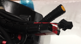
The recent BBSHD has two addition connectors from the controller. One Higo, Gear Sensor and one JST. WHY the JST????
 
fechter said:
So water can get in? I haven't seen one like that.
That's the report I got. I'll get a picture to confirm. He fellow may have mistaken another connector for a JST. However there IS a second connector besides the GS and usual. Did they comet with a light connection? I guess I'd better ask for multimeter readings as well.
 
Alan B said:
There is a 3 wire JST connector on the Luna dual speed hubmotor controller as well. I don't know what it is intended for. The other connectors on this controller are Higo. Luna should be able to answer that question, I haven't asked them.
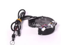
Being a apostate, an answer isn't possible.
 
Yup, it's a higo, having him test for power...
Only Bafang...
Nothing like a nice waterproof connection choice....JST? WTF?
 

Attachments

  • Screen Shot 2017-05-30 at 3.19.51 PM.png
    Screen Shot 2017-05-30 at 3.19.51 PM.png
    158 KB · Views: 4,230
JST plug will output 6 volts when the lights are turned on on the display.
 
Apparently Bafang is unpredictable and did a 6v higo on some 02 version, and the jst last year..
https://endless-sphere.com/forums/viewtopic.php?f=28&t=85082&p=1246609

And i posted in it. :roll:
 
fechter said:
So it's a headlight connector?
Yes, with some displays there is a light option. Not sure which but definitely with the first color and the recent horizontal. I don't remember if the 965 has a light option. I think the DCP- 10 and DCP 14 do. They're in my spare box, I'll hook all up tomorrow to check and confirm. Unless someone else chimes in.
Hopefully I can find someone to trade controllers. I have a GS HD controller for back up. I really don't like the GS and never use them (have 4 or 5 around here from the original testing days) it's just my back up. BUT I like the 6V light JST idea. Even if it's a poor choice for waterproofing.
I'd use it for a LED flashing tail light.
 
fechter said:
So water can get in? I haven't seen one like that.
I'd sure expect it would. I'd definitely treat it with Boeshield and give it a tight shrink tube.
 
Alan B said:
If it is a 6V supply for a light, a little current leakage from water would not matter much, it is not an input signal that would be corrupted.

A bit of silicone would make it repel water.
Couldn't short out?
 
The current flow follows ohm's law I = E/R. The resistance of water is not that low, though it does drop with contamination, but it would not likely be a large current flow at this low a voltage. It could cause corrosion if it continued for a long time, and that could be a problem. Moisture is more of a problem with an input such as throttle or brake where a small current flow can change the signal and cause problems. Or with a higher voltage where the current will be much larger or even be a safety hazard.
 
Nothing would short out, but you would possibly get some nasty corrosion happening on the connector if the water bridged the pins.

I don't think that output can handle a lot of current either. Fine for a tail light, but I don't think you could run a 20W headlight off it.
 
So about all its good for are some German dynamo, expensive, lights? Still looking...

http://www.custommotoredbicycles.com/lights_led_headlights_chrome_bulletblack_bullet
 
Does anyone have a picture of a BBS02 o BBSHD controller with the extra headlight lead or know on the controller where it attaches? I have a Bafang/Lunda Display DSP-18 that includes a headlight switch?

ATTACH]


I've heard discussions that the extra wire is only 5-6V at 500mA and not enough to power a light. I assume it is just a signal circuit to close a relay. I was intending to do this all along using a separate switch, but, it would be very nice to just use the one with the display to cut down on clutter.

I have a BBSHD that doesn't have the extra headlight lead coming out of the controller. I'm wondering where this lead attaches on these controllers and that if even the ones that don't have the lead have a place where one can be attached. In the picture below, I can see the long leads that come out of the controller and I can also see a few smaller connectors inside of the controller. I'm wondering if either of these might be where the headlight wire attaches. I see on the picture that one of them is even a JST connector as the headlight wire seems to be when present.

ATTACH]


Even if these connectors are not where the headlight connects or are not present, does anyone know where on the board itself a headlight wire would connect (assuming they all use the same board).

It also looks like things may be sort of sealed. Anyone know anything about this?

I haven't opened my drive up to look yet. I guess I could just be an extra controller and play around and if successful I'll be successful and if not I may either destroy it or have a spare. It would be easier to know ahead of time though. Anyone with one with this headlight wire ever opened up the case to take a look?
 

Attachments

  • bafang bbs02 controller_w_connectors.png
    bafang bbs02 controller_w_connectors.png
    59.5 KB · Views: 3,458
tmort said:
Even if these connectors are not where the headlight connects or are not present, does anyone know where on the board itself a headlight wire would connect (assuming they all use the same board).

I haven't tested this, but I'm pretty sure the headlight connector is this one:

BBSHD Headlight Connector 1.jpg

On the bottom side, you can see the little transistor that turn it on:

BBSHD Headlight Connector 2.jpg

The transistor doesn't look like it can handle much current. It appears to be switching the B+ coming from the pack. There does not seem to be any current limiting or protection, so if it shorts, there will be smoke. If your controller is potted, you might be able to dig out the potting around this spot and solder to the board. You can also look to see if there are wires already coming out of that spot.
 
Thanks,

That helps a lot. I'm finally getting around to putting together bike I started a number of years ago but there were a number of distractions. I had (and still have) a hub motor and Lyen controller. I made a few attempts to get back to it, but, the rats nest of wires (unlabeled by me of course) and the problems arising from that as well as new distractions kept it from getting together.

Meanwhile things changed and mid-drives became a thing and I saw the Bafang system so I changed course. It got rid of a lot of wires, but, weight distribution, etc.

I think I'll order a replacement controller and work on adding a headlight wire to it. If I'm successful I'll install it. Then I will have a spare controller on hand as well.

You mention there is no over current protection in the circuit. It seems like if you wanted to put a fuse on it you would put it in front of the transistor, but, as I thought about it more it seems like maybe I could just add one as a line fuse. Any thoughts?
 
Seems like it should work to just put a fuse in line with the wire coming off the board. Wild guess 0.5A.
 
Thanks, I'll give it a try.

Also, I mentioned the rats nest of wires on the other controller I was going to use (and still might for something else). I just happened to get a newsletter or something that included a story on a new line of connects that sounded intriguing, but, I really haven't looked into.

This thread might not be the right place to mention it, but, I got to thinking about it and thought I'd pass the info along.

It is a multi-conductor connector that is also hybrid as it has both signal wires and power wires all in one cable. I'm not sure how you would go about making a harness with branches coming out at different places, but, it might be something of use.

https://www.phoenixcontact.com/onli...4b047520/e5b188be-3b52-4b08-ae3a-80694b047520
 
I'd been putting off trying to remove the potting as it sounded difficult. I happened to be flexing some of the larger power wires on the assembly one night and I noticed that when I did this the potting sort of pulled away from the housing. I pulled on it a little more to see what would happen. I didn't all just peal off, but, it did come away from the housing and wires and so forth. It looked like I'd make a mess, but, that it might not be too hard.

The potting must not be silicone. It is flexible and rubbery, but, sort of brittle. I was able to break it into small bits with a plastic pointy electronics tool that came with a soldering iron.

I'd wondering if anyone knows what type of potting this might be? I plan on re-potting it and I'd just as soon use something that can be removed fairly easily in the event I need to make a repair or something. I imagine there is some amount of heat resistance needed, but, don't imagine it is considered a high temperature application.

I'm also wondering about soldering the wires onto the board at the point that was suggested. At least for the time being I gave up on trying to remove the board from the aluminum housing it is in. It looks like I might damage it it trying to do that.

In looking at the pictures and in person from the top view it appears that at the switched spot there are holes for a wire going through the board. In person it looks like the holes filled with potting. I first thought I would drill through this to remove the potting in these holes, but, I remembered the picture of the other side of the board shows a transistor. In looking at the picture of the backside it appears this transistor is right over the hole. Drilling out the hole doesn't seem like such a good idea if that is the case. It is hard to tell with the picture what exactly is on the other side and like I said, I'm afraid I'll do some damage if I try to remove the circuit board.

I'm thinking of just soldering directly to the metal contact points on the surface of the board. After I pot it again, the potting will help secure the wire in place.

Anyone have any suggestions or advise on this? Is there a trick or technique to removing the circuit board and not breaking anything?

TIA
 
The potting is some kind of silicone stuff but it is easy to dig out. You just need to be really careful around the skinny wires that are embedded in it as they could easily break. I've never tried completely removing the board, but I have seen others do it successfully. There are two screws holding the ends of the curved heat spreader bar that need to come out. After that, it's just the potting holding it in. Use a tiny screwdriver or blade to go around the edges and try to separate it. If you can find a way to pull on the heat spreader bar, that is well attached to the board. You can also push up on the bundle of wires and maybe try to get something under the heat spreader bar to pry up. Avoid prying on the board itself.

You might be able to make attachments to the holes without removing the board, but it will be challenging due to limited access and tight spacing between the holes. To attempt this, I would clear out around the connection to expose the holes and make sure there is no potting just below the hole. A tiny drill could be used to clear the potting, but it could also damage the through hole plating, which would be bad. It would be better to use a smooth stiff wire and just poke through the hole. Once the holes are clear, tin the end of the wire to be soldered and make sure it will fit through the hole. Then insert the wire just enough to get through and bend it over so you can get good access with the soldering iron. Then just use a little ball of solder on the tip and heat until it flows. The wire insulation will tend to melt, so check to see it isn't shorting against anything else on the board. Teflon or silicone insulation won't melt.

If successful, you put it all back together and test. The potting may look like a mess, but I really wouldn't worry too much about it. It really only needs to cover the surface of the board. Personally, I wouldn't try to add new potting since I avoid riding in the rain anyway. If water is a real issue, then you could use some silicone or conformal coating, but it will be pretty hard to get off later if needed.
 
Thanks!

I try to avoid riding in the rain too, but, sometimes it happens. I am also planning on embedding a panel mount fuseholder for the short little (obsolete) 5 x 15mm glass fuses in the potting. The holder should just stick out of the potting a little bit. It might not be the most convenient location if I need to change the fuse, but, it puts the fuse in the best spot and keeps it out of harms way.

With the further instructions on removing the board I'll take a look at attempting to remove it. I just sometimes get impatient and try to force things. I'm sure I can remove it, whether I break it in the process is another thing.
 
I had some trouble with lighting/magnification to see what I'm doing and other more urgent things came up. This project sort of got buried. I'm just getting back to this.

I have chipped away all the epoxy I can see and get to. I was able to move the heat sink a little with a tiny flat blade screwdriver.

I was thinking of drilling some holes and tapping them on the top of the heat sink and then attaching something I can grip to pull them it and the circuit board out.

I got to thinking I could actually just use some of the screws on the side holding what I assume are the power transistors on for this to attach something I can grip. I'll have to look around for an offset screwdriver and some metal before I do this though. I thought I might as well post this here to see if anyone has any thoughts on either of these ideas or any other suggestions.

Thanks.
 
Back
Top