Sanity check please: 3x AquaStar T20

rajien2

1 µW
Joined
Jun 20, 2017
Messages
4
Guys,

I'm on my 43rd apple battery 'recycle', I current have ~240 1900-2010 mwah 18650's and 32 more packs to disassemble. As a result I think im ready to start looking at a power plant, taking inspiration from the following videos I think 3 motors would be amazing.

https://www.youtube.com/watch?v=UG8RsJsJ05I
https://www.youtube.com/watch?v=yfn_HKViwtM&t=194s
https://www.youtube.com/watch?v=SiiNORLzA18

I need a bit of a sanity check on this set up, ive gone with water cooling options for better thermal control.

Motor: Turnigy AquaStar T20 x3 (229A) : https://hobbyking.com/en_us/turnigy-aquastar-t20-3t-730kv-1280kv-water-cooled-brushless-motor.html
ESC: Turnigy AquaStar 200A Watercooled x3 : https://hobbyking.com/en_us/turnigy-aquastar-200a-watercooled-sensorless-esc.html
Battery: 18650 x348, 29 cells in a module x12 at 44V at 696,000 mah
Frame: 140 Moto FRAME KIT with Larger Shield https://qulbix.com/qulbix-products/diy/frame-kits/140-moto-frame-kit-with-larger-shield
Throttle/Thermal control/BMS and rate sensor: Arduino Edison with a surface pro display.

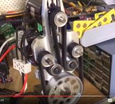
The motor set up would look like the picture bellow. I believe with a large enough pully I can get the RPM down for more torque... Let me know if anyone sees any glaring problems with this configuration or if you have a better recommendation
 

Attachments

  • Capture.JPG
    Capture.JPG
    50.7 KB · Views: 2,228
what are the cells? they arent all created equally. The RC motors love a lot of amps.
 
Sean9002 said:
what are the cells? they arent all created equally. The RC motors love a lot of amps.


Hey Sean,

Yeah they are 18650's rated around 2.5+ amps, at full load all with 3 motors it will be pulling 687 amps (Per sheet). So at 348 cells they should be able to handle 870 amps if I understand correctly.

The cells are from apple G3 G4 12" A1008 A1061 M8433 packs and are a mixture between:
icr18650J http://www.houseofbatteries.com/documents/ICR18650J.pdf
ICR18650-22F http://shop.battex.cz/pdf/CMICR18650.pdf
US18650GR - some vaping forum says 4.4 but I feel better saying 3 amp.
Red cell green cap - No spec sheet on this but red = Sanyo and being that they are coming from the same packs as the others I would say 2.5-5 amp discharge.
 
rajien2 said:
Sean9002 said:
what are the cells? they arent all created equally. The RC motors love a lot of amps.


Hey Sean,

Yeah they are 18650's rated around 2.5+ amps, at full load all with 3 motors it will be pulling 687 amps (Per sheet). So at 348 cells they should be able to handle 870 amps if I understand correctly.

The cells are from apple G3 G4 12" A1008 A1061 M8433 packs and are a mixture between:
icr18650J http://www.houseofbatteries.com/documents/ICR18650J.pdf
ICR18650-22F http://shop.battex.cz/pdf/CMICR18650.pdf
US18650GR - some vaping forum says 4.4 but I feel better saying 3 amp.
Red cell green cap - No spec sheet on this but red = Sanyo and being that they are coming from the same packs as the others I would say 2.5-5 amp discharge.

Yes if you put all 348 cells in parralel then multiply that by how many you have in series...348 X 13 (13s will give you the voltage you cited) giving you 4524 cells.
Repurposing laptop cells is the hard way, not the easy way, you can go high voltage with low amps safely, but your looking at doing the opposite. . What ever you do, DONT LISTEN TO VAPING FORUMS REGARDING BATTERIES!....we use them very differently to how they do. Im not saying theyre wrong, they just dont understand our application. you will be drawing the full C rate (if not more) for extended periods of time...longer than a [strike]douche bag[/strike] person can hold some vapour in his lungs :lol: . The ICR18650-22F cells are rated at 1C...they have an absoloute max discharge of 2C

All in all this could work, but your risking killing half the pack the first time you make a loaded draw of current....that; or a catasrophic fire ball! :twisted:

The tripple setup that Bruno is using is powered by RC lipos that have a discharge rate 65 times higher than the cells youve proposed.
 
Sean,

Thanks for the information im glad I checked with you guys first... I assumed that the 4,400 mA or 4.4 amp discharge would be counted with all the cells together IE 4.4 x 348 being 1,531 amps total being the ceiling of the whole pack. I also assumed putting 12 3.7v 'subcell' of 29 cells together would get you to that 44 volt mark and your total 'tank' would be 348 x 2,000 mah or 696 ah. From what im taking away from you is, you need to count each subcell as only 2C so 4,400 x 12? being 53 amps? If so does that change your tank number too? I apologize if this is a rudimentary set of questions...

Thanks
Cody
 
rajien2 said:
Sean,

Thanks for the information im glad I checked with you guys first... I assumed that the 4,400 mA or 4.4 amp discharge would be counted with all the cells together IE 4.4 x 348 being 1,531 amps total being the ceiling of the whole pack. I also assumed putting 12 3.7v 'subcell' of 29 cells together would get you to that 44 volt mark and your total 'tank' would be 348 x 2,000 mah or 696 ah. From what im taking away from you is, you need to count each subcell as only 2C so 4,400 x 12? being 53 amps? If so does that change your tank number too? I apologize if this is a rudimentary set of questions...

Thanks
Cody

You really need to go through and test each cell individualy to find out what its capacity is, this is done even on brand new cells fresh from the box, used cells, its even more important. Whats on the outside, may not match the inside and this could be true for cells from inside the same pack.
Im an IT technician and have seen inside most major manufacturers packs for the last 6 years, they all have very low C rate cells, they all use VERY think nickle strip connecting cells (not good for a high amp environment). as an indicator, lookup what the peak power consumption of the laptop is, while only on battery power, it will not be much.
It gets confusing if you try and think of it in terms of fuel, it doesnt behave the same. At different points of discharge you could be making less power or asking more of cells for the same amount of power (battery sag), not like fosil fuel that always contains (roughly) the same amount of energy per volume for a given fuel. If you come from an automotive background think of it like this: The setup youve envisioned is like a High RPM rotary motor. If you want to have crazy power on tap, you need a crazy fuel system, race fuel, high capacity pump and injectors. You wouldnt build a drag car and say "ill just run stock injectors and run low RON fuel".
Before you embark on this project, you need to surf through the forums, there are dozens of great threads where people have made packs in a simmilar fashion, but they havent asked as much of the battery. If you want to use a high power setup you need a high power battery, that has cells capable of high discharge, either a BMS or a good working knwoledge of batterys to prevent failure sans; BMS, otherwise they will fail and you could get hurt badly.

If i were to use the setup youve discussed running an 18650 cell your looking at Samsung 30Q's, Sony VTC's, or preferably a high discharge RC lipo setup.
 
Sean9002 said:
rajien2 said:
Sean,

Thanks for the information im glad I checked with you guys first... I assumed that the 4,400 mA or 4.4 amp discharge would be counted with all the cells together IE 4.4 x 348 being 1,531 amps total being the ceiling of the whole pack. I also assumed putting 12 3.7v 'subcell' of 29 cells together would get you to that 44 volt mark and your total 'tank' would be 348 x 2,000 mah or 696 ah. From what im taking away from you is, you need to count each subcell as only 2C so 4,400 x 12? being 53 amps? If so does that change your tank number too? I apologize if this is a rudimentary set of questions...

Thanks
Cody

You really need to go through and test each cell individualy to find out what its capacity is, this is done even on brand new cells fresh from the box, used cells, its even more important. Whats on the outside, may not match the inside and this could be true for cells from inside the same pack.
Im an IT technician and have seen inside most major manufacturers packs for the last 6 years, they all have very low C rate cells, they all use VERY think nickle strip connecting cells (not good for a high amp environment). as an indicator, lookup what the peak power consumption of the laptop is, while only on battery power, it will not be much.
It gets confusing if you try and think of it in terms of fuel, it doesnt behave the same. At different points of discharge you could be making less power or asking more of cells for the same amount of power (battery sag), not like fosil fuel that always contains (roughly) the same amount of energy per volume for a given fuel. If you come from an automotive background think of it like this: The setup youve envisioned is like a High RPM rotary motor. If you want to have crazy power on tap, you need a crazy fuel system, race fuel, high capacity pump and injectors. You wouldnt build a drag car and say "ill just run stock injectors and run low RON fuel".
Before you embark on this project, you need to surf through the forums, there are dozens of great threads where people have made packs in a simmilar fashion, but they havent asked as much of the battery. If you want to use a high power setup you need a high power battery, that has cells capable of high discharge, either a BMS or a good working knwoledge of batterys to prevent failure sans; BMS, otherwise they will fail and you could get hurt badly.

If i were to use the setup youve discussed running an 18650 cell your looking at Samsung 30Q's, Sony VTC's, or preferably a high discharge RC lipo setup.

Hey Sean,

Thanks for all the information, I also work in the IT field as a sys admin so my electrician experience is limited. It sounds like I need to revisit my design and do some more reading... I still have months of balancing and discharge testing on the cells i've gotten in. The ME4201 might be a better alternative, Thanks again for all your help.
 

Attachments

  • charge.jpg
    charge.jpg
    38.3 KB · Views: 2,101
No worries! Good luck with the planning! looks like youve got it covered.

Keep us posted on your build! Would love to see a tripple motor setup
 
Those motors are 730 KV, I have no idea how you plan on lowering those RPMs to a usable value.
my guess is you can't so the whole power potential of them doesn't actually exist.
3 sk3 motors wouldn't please you? :)
 
For High Amp Draw like anything over 50 or 60 amps , I would use High C Rate Lipo's.

Like ones rated at 45 C Rate, or even ones rated at 65 C Rate for the kind of high amp draw that you are talking about.
 
My thoughts on this setup:
Some assumptions are not correct, max current of motor is 128A in wye (not 229 which is only for delta). Max volt is 41. These figures have to be respected as hobbyking always blows up their specs. Go above either for a longer time and the motor will blow. A reasonable rating for any hobbyking motor is to take half the specified power as what can be used more than a few seconds.

750kV and 41V gives more than 30000rpm, it get's complicated to reduce down to a useful rpm. You'd need to get it down to 500-1000 rpm so design between 1:30 and 1:60 reduction. It's doable with a two stage reduction but not in one step. something like 1:5 belt --> 1:10 chain. Minimum recommended pulley for the belt is 22t so large pulley would be 110t, that's expensive.

Pros: it would be fun to design, look complicated and cool and sound like a jet engine.

Cons: It's complicated, expensive and sounds like a jet engine. The high pitched whining noise will get tiring in some time.
Total cost is high for what you get with all the bits and pieces that's needed.

The setup in the picture is not a good belt drive, the sharp bend angles on the belts and the counterbending lowers durability. Belt will crack as a result - within time. For racing or as a design study it could be done but i'd personally not invest time in it as it will break too often.

The torque of each motor is only 1.6Nm at full current so you'd get away with narrow belts and pulleys.

I can recommend contitech drive designer program:
https://www.conti-professional.com
It's free, you just need to sign up.

If you're into the techie design just for the tech of it then i think it would look nice to have motors equally spaced around the first stage of the reduction (on a circle, 120 degrees apart). You'd need 3 belts, 6 pulleys and a jackshaft to do this off course but that's about the same that bruno has. or maybe connect a gearset to the three motors.. :D
something like this but with motors instead of cylinders:
osmg1307.jpg
Good luck!
 
Back
Top