Shaft adapter, splined and threaded for freewheel and cog

MattyCiii

100 kW
Joined
May 5, 2007
Messages
1,374
Location
Boston, MA, USA
Thread resurrection.

In the 3 years since I started this thread I've made some design changes. I'll document them all later, but here's at least one detail: I'm going to mix RC drive electric power with human power using a jackshaft, behind the cranks and concentric with the rear suspension pivot.

Picture if you will: the jackshaft will double as the suspension pivot. Using a freewheel, electric power will be put to the shaft on the left side of the bike. Also using a freewheel, human power will be put to the jackshaft on the right. A cog fixed to the shaft will send human and/or electric power to the rear wheel via a chain...

Believe me it all seems to work in my imagination!

So, using as many off the shelf parts as possible - especially parts that wear such as cogs and freewheels - I'm designing a freewheel/cog mount for the 1/2" jackshaft.

Below: a 1/2" shaft. Placed loosely on it, a Shaimano 9-splined adapter (for human input to a NuVinci hub, used here for example). Below that, a freewheel adapter from user Recumpense: thread on a 30mm freewheel, two set screws fix the adapter to the 1/2" shaft...

Wp6CXMgrmsbIgCmXjTRio9n4_slKIvgql3_KtlKwTeHIkBcGPd7U_HdAvq264DDwgqHrRyZNUoqndw=w330-h440


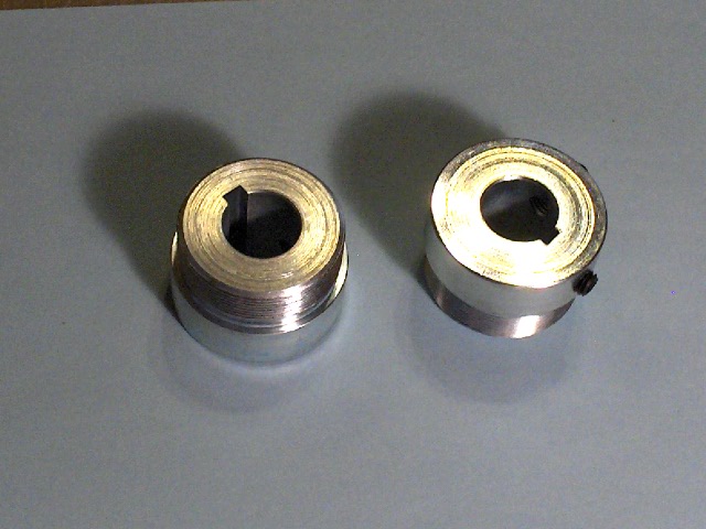
Here's a picture of the Recumpense freewheel adapter showing its set screws. Note: this is a 1.375" freewheel on a 30mm mount, so it's just haphazardly friction fit. That's why it's crooked in the picture!:

Vw0_IxYFND7vIdhb9897pxQqGBpgEqjezOYiQD3hNepKzCG583EBTKAAk5w1lkHMi5VeaqCWKXEX7g=w330-h440


I don't have a lot of space to work with so things have to be mashed together. The mounted cog and freewheel will look a lot like this:
cSYN20AvmXA_VhwBzO-YTNmBPom5rIO5OJ4ZzwezhkxrJfI8W9Vph0xZQUJDobeEcpmV1KCZxqc8lw=w330-h440


Here's the part I have in mind: half of it is a 1.375-24 threaded section for a screw-on BMX freewheel, the other half has two 90 degree offset set screws to fix the adapter to the shaft. Once the adapter is affixed to the shaft the fixed cog slips over the splines and is held in place with a big "C" shaped spring clamp. Here's the problems this solves:
1. After awhile, freewheels are very hard to remove, because putting power to through them makes them thread on tighter.
2. So to remove a freewheel from an adapter, in the past I've had to put the adapter in a vice to unscrew the freewheel. In the future I hope to use a chain whip to hold the cog in place to remove the freewheel
3. Worst case, it'll always be easy to remove the cog and loosen the set screws to take the adapter off the shaft so I can work on it off of the bike...

Q9eay42L6kYmJjpzvHhFxSAIdYX4ad_jNSktoqVpgTRkMz4f-HX_HsYvmW26tn_uH-kYUMBU4PcD9A=w538-h440


Here's the cog. It has a 9 spline interface that would work with a Shimano cassette interface. The NuVinci N360, 380 etc use these cogs.
3j10Sr6QPPqx3LHBT-fU5NBFb8v5zj73HEioA1Huc8cAkWSWkVCaD3fDeubJNGWkeppil3LgCUPqwg=w586-h440


This is a NuVinci freewheel with the cog placed on it. It's a wear part (should the bearing fail or freewheel pawls wear), inexpensive and replaceable. I'm using it because it looks like what I need...
4HO3kDZdQ1GDdud71ikrz8DyQawwGEzTM-vkhQhUZwiWFtawFka2vDtTes4qyY8vrlVE9P2BYpWPbg=w586-h440


Here it is with the ring clip in place, keeping things nice and tight:
SqfI8XUWlbFEMCrtK-Y62v2sYNR-T8dWsX4thEBe_jpvbyp0LgZ3sKe1AumoyfHXf0vjNgx065_EbQ=w330-h440


Why am I bringing all this up? I'm going to have some of these parts made. I got a quote from eMachineShop.com for $40 per adapter, as long as I buy 10. They're about $150 each if I buy 2 (I need 2 for my next bike).

Interestingly, a much simpler part - one that simply has 1.375-24 thread the whole length (because I could simply just use a thread-on cog) costs almost the same amount...

So I'll write a new post with some specific machinability questions to the machinists out there sometime this weekend. Stay tuned!!

8296
 
OK I'm soliciting advice. If I can have this part made for a reasonable price, I will be moving forward with my next build. Here's where I need the help:

  • Material: I definitely don't want the part to deform under load. Would 6061 or 7075 aluminum be OK? If not, what's the 'best' material to use (steel obviously - but what grade?). "Best" is the sweet spot between machinability, cost, resistance to deformation... (what other considerations should I have in mind?)
  • What's the best way to actually make it: more info below
  • How to go about specifying the job: more info below

Details: I have about 5 inches of horizontal space in which I have to fit: the suspension pivot, 2 freewheels & a sprocket/cog. I also have to worry about chain alignment. This is why I'm designing a custom mount - I want it to take up as little horizontal space of those 5" as possible.

Here's a rendering of what it should look like all put together:
aOqxiq13Gjkugeh6xF8XxArOzyt9678XfEAyyl6QXfXamm91rZBLZDTpDJI1L-gRKkuldL5yy2d2KA=w430-h440-rw

That shaft can be driven by electric power (not rendered - "off camera" to the left in the picture). When that happens the sprocket shown drives the main chain to the rear wheel, and meanwhile the freewheel... well it freewheels. The freewheel pictured takes power from the human drive, and will transfer it to the sprocket.

I learned from my current RC drive bikes that replacing freewheels is necessary from time to time. It can also be a real pain. Freewheels practically become fused with the mount because they "screw in" while power is applied. This is why I have the set screws placed such that they are accessible when a freewheel is fully threaded on. This allows me to remove the FW mount and place it in a vice to remove the freewheel.
IjhqFTdg5Y22C7TxDeJ-IJK0O02EfnEn1HyGAy_XRK8_piT-H1k4WHmY3awV9I0OsaZxFo84lTwoOQ=w488-h440-rw

0_HWQaJXNr6FHAGm0YOTrcdPZ8laQ0xfwNeylkVU_lNTHx57d4G-GzTVJLYkbB6ABIy1oZyRIvs1Xg=w578-h440

YMj_If_TpsXj8mhICv4rfIQ5mSd0K12EUcYhDp_LZ1VmkO7lSscZeHhQlhVKxJv4w44O93QM6TxZHg=w548-h440


So here is what I designed as my "optimal" shaft adapter. But is it easy enough to manufacture? Would alternative approaches lower the cost appreciably? And how do I articulate to the machinist what compromises I'm willing to make to lower the price of the part?

The red arrow in the pic below shows a 'shoulder' the sprocket braces against, so that the sprocket is held firmly in place axially when the circle clip is in place.
UJpwO4z_ac4QphyeU1F6zBcH3YV7o6TTXWs_YMSowl_iEn6H3vmWPBtzzIzSRbH8fNePvJ6JxDGQuA=w434-h440-rw


Manufacturability:

I probably don't need a full 11.5mm of thread to firmly hold the freewheel in place. So I'm thinking - if the 9 spline interface is milled into the part with a spline cutter, it's OK for the cutting tool to taper off part-way into where the freewheel threads are.
hSL140v52UuOFmaQsLnzoEmk2by1Hao-h4LCg4AhBfqS8fKcUuciSHnCj4LZ3RvNxm5n40MT4oQ3vg=w600-h440


Or if the splines are milled into the piece as shown, again it's OK for the end mill to cut into the main threads a bit as shown by the red arrow. How far? I don't know!
7WHFDlGZEiQCTHYM8jYtEUi1IxJTY6DtJSSjGBOz5V3V_m5fugt3yKARSvdoeDTXUqp_efw2Uvq1Rw=w594-h440


Maybe the splines can be cut all the way. And the threads can be cut all the way for that matter? I would be concerned though that the threads will weaken the surfaces that transfer force to the drive sprocket (red arrows).

StcyVqihSxMYvcjM-GATkghhveuaSd8accmBVQO2YeyymUurPTfVCQGfOyD8VvnI8iUaaQk1RFF63Q=w382-h440


In these above scenarios, I'm counting on the freewheel "bottoming out" onto the adapter (the red arrow, below, points to the face that will 'bottom out'). I would then slip a 1mm thick shim onto the freewheel adapter (to space the sprocket away from the moving portion of the freewheel), slip the sprocket on the assembly and lock it in place with the retaining ring.
XkU5iIsFTHYsk8OlKC26mZ0p4JAfKYPIeSRhbCTgh0hSNOVYsy2kkFIAPupn7DnuhZbfBhERyrzthw=w494-h440-rw


Final thought:

So from my spline pattern you might think I'm being unnecessarily faithful to the shape of the Shimano freehub shape (see smaller spline circled in red):
syCR0rtKB444owMd9uH3uCOCiV4wE9EMGPjd4m7ir6-KSWYZmFjieaReUYH7i7lG1V3yLxAWc5sn_A=w460-h440


But single speed cogs don't require this asymmetry. I looked at several manufacturer's products.
3j10Sr6QPPqx3LHBT-fU5NBFb8v5zj73HEioA1Huc8cAkWSWkVCaD3fDeubJNGWkeppil3LgCUPqwg=w586-h440


Well, I'm not doing it to adhere to convention. I'm doing it because I have the set screws offset by 90 degrees, and to make threading & tapping the set screw holes easier, I provide an even surface - which coincidentally leads to matching the Shimano spline pattern:
MKmC0CBIeNYTto8kMS1zzMAFIju2pqfbNJHZBqCSl7e6fSJUZZa7nTU_dmGNvZ4pTHTw80EmSRw-HQ=w598-h440


But since I'm grinding my own flats in the shaft, I don't actually have to have my set screws offset by 90 degrees. I could just as easily offset the setscrew holes by 80 degrees, or 120 degrees, and thus have flat surfaces to drill and tap. Any thoughts on this approach?

Any & all comments welcome!


8457
 
How about using a cog with a six hole disc brake interface instead of cassette splines?

http://www.velosolo.co.uk/shopdisc.html


file.php


Making six tapped holes is a lot easier and cheaper than machining the splines.

As for material choise, I would use either 7075-T6 aluminium or 17-4 PH stainless steel.

Avner.
 
ferret said:
How about using a cog with a six hole disc brake interface instead of cassette splines?

Making six tapped holes is a lot easier and cheaper than machining the splines.

As for material choise, I would use either 7075-T6 aluminium or 17-4 PH stainless steel.

Avner.

Thanks Avner! I'll look into this as an option. Much appreciated.
 
OK, I'm maybe beating a dead horse here continuing to refine this design, but:

1. I'm learning Autodesk Fusion 360. Drawing different parts - and drawing the same part over & over- is helping me learn the program.
2. I've been watching some 'machinist porn' on youtube - lathe work and spline cutting, etc - and I think I've learned a meaningful simplification of the shaft adapter design.

My previous iteration "optimal deign" had a ridge/shoulder in the middle. Its purpose is for the cog to brace against. But looking from the other direction, threads are cut right up to that shoulder. After learning a little about how threads are cut on a lathe I now understand that cutting threads right up to a shoulder is quite difficult to machine. It's better to cut threads up to a groove than up to a shoulder. The red arrow points to the shoulder:

UJpwO4z_ac4QphyeU1F6zBcH3YV7o6TTXWs_YMSowl_iEn6H3vmWPBtzzIzSRbH8fNePvJ6JxDGQuA=w434-h440-rw


My new design has a groove where the threads end, hopefully making it easier to machine:

-ufDRdeFxPd4_1ECM2r1i8ecUL0PWGmTFyczA0tXAF7PIiYZBL5d8ArX3TsUPhmWDN93_KsNYv3nEA=w488-h440-rw


Fusion 360 has a real easy feature that allows you to import 3D STEP files right from the McMaster-Carr catalog. So that's what I did to get this model of an off-the shelf retaining clip I'll use on either side of the cog. These retaining rings come in two thicknesses: I'll use a wider one where you see the wider groove, near the threads:

CBtjuw0xs36WJAEhu3r9KVPIyp9cXCixzGkoYTAu8sA_rsRtrK5Ac0spYVW583Ii9q9GqJnRY4Xy9Q=w436-h440-rw


Here's it is as an assembly, with the thicker retaining clip in place and other parts 'exploded'.

jRfY95Q7sLBTKP3sWPk6XM3rNLLpTTd0W3q2twVBKk8JOZdA80nkFeS01LaUwdwI_QMvHCocYIUlGA=w684-h440-rw


Two final thoughts:

1. If made out of the proper materials (7075-T6 aluminum or 17-4 PH stainless steel, etc.), each adapter should last the lifetime of the bike. They should outlive many cogs and freewheel replacements.
2. I plan to use 2 of these on my next bike. Strictly speaking, I only need one of these per bike plus another off-the-shelf shaft adapter for a freewheel. But that part is $80 if I recall correctly, and in my experience when you have something custom machined, buying more copies of the same part drives the per-part cost down. I'll probably order 8 to 10 of these things, because if it works as expected I can see myself building at least 2 bikes with this design and I want extras for spares, or to sell to interested EX members.

Thanks for looking, I hope I'm not spamming the 'active topics' list too much with my frequent updates... :lol:


:pancake:
 
Look up "thread milling". It allows for some interesting possibilities.
Thread mills can start or stop a thread right up to a shoulder.


Sent from my iPhone using Tapatalk Pro
 
Staton carries a number of freewheel thread to shaft adapters, this one is $12.29 and might even have enough material to cut the splines/grooves in the unthreaded part.

http://www.staton-inc.com/store/index.php?p=product&id=986

0041.jpg
 
7075-T6 aluminum or 17-4 PH stainless steel

Even though you are clearly doing some great research ahead of time, I'd still recommend 7075 aluminum for the initial units. Simply because they are easier to machine, and you may be surprised at a new idea popping into your head after you've ridden the prototype a few weeks. Nothing wrong with having two versions, but I's still wait on Stainless until I was verified very happy after many miles to go that route.

Once you show the build running, you can order a new part in SS, and easily sell the aluminum proto...

OK, I'm maybe beating a dead horse here

Now you're speaking my language. Whenever you're in the mood to beat dead horses, PM me and I'll make some coffee.
 
Interestring adapter. And if you make a batch of them and have surplus count me on one at least.
Wonder what's the adapter ID and total depth.
As about the material. 7075 would be probably more than enough. The only possible flag I see, just to be the devil's advocate, even with the snapring, is a possible small but crucial amount of wobble of the splined unit compared to a threadlock system. This should be nothing for a SS adapter, but could count a bit with any alloy especially if the splined unit is steel. I see the cog has a wide base so perhaps this will not lead to any problem hopefully.
 
I like the idea a lot, but other than for a set up "sample" or proof of concept, i wouldnt go near an alloy for any spline drive set up...It just wont last any time at all.
Mild steel is no harder to machine , and probably cheaper...you might even consider a flame hardening steel for a test/ final product.
And Yes , mill those splines right through the threaded portion if necessary...but dont thread the splined area,..you need max metal there.
 
Thanks guys!
This is a very big help. I have a slight refinement off the design in the works and the advice on material choice is greatly appreciated!
 
Back
Top