Samson
1 W
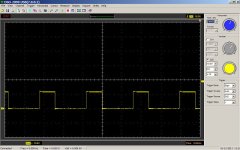
 I built my first E-bike last week and it seems to run okay but I just poked an oscilloscope probe on the motor phases and Hall outputs and things do not look well. The image is of a scope trace with the one Hall output on top and one phase on the bottom trace. There are spikes of significant width that descend to zero volts. All three phases and all three Halls have the same pattern on the scope.
 The spikes look the same at part throttle. That is they are in the same place and have the same amplitude as at full throttle waveforms more or less. I filtered the Hall signals with small capacitors thinking the Halls may be causing the phase spikes and this cleaned up the Hall signals but this did not help the spikes on the phases. The Controller is A Golden motor magic controller and a Golden motor 250 Watt, 36Volt geared hub motor. Battery is a 40 VDC Headway pack. All wiring is very short in length. As I am new as this I am not sure what to expect from the waveforms but this does not seem right to me. The scope was connected from the battery Negative power lead at the controller to the Hall and Phase controller pins. Any ideas?
Ken

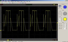
") looking at the yellow trace in the image you can see that the timing is off
looking at the yellow trace in the image you can see that the timing is off