Relay wiring question!

lazarus2405

10 kW
Joined
Sep 5, 2007
Messages
782
Location
Rochester, NY
So, I'm using a relay so i can activate a high current connection with a small MOM NO switch (aka Little Red Button). So, how can I easily power the relay? I have a CA and Hall throttle on my handlebars. Can I use one of those, and if so how could I tap into one of them (which pins/wires)? Preferably the CA.

The relay's info is as so:
Nominal coil voltage: 12v
Nominal coil current: 75ma
Coil resistance: 160Ohm
Pull-in voltage: 9.6vdc max
Dropout voltage: 1.2vdc min

Specifically, what do those last two specs mean for a relay?

Also, I just bought a trim pot that has three pins. The third, middle one is labeled "wiper". What does that mean?

Edit: Ohhh... I get it. A 1kOhm trim pot has a length of resistor connected to two pins measuring ~1kOhm. The screw moves where the third, middle pin contacts the resistor, from near one end to near the other. As the screw turns, resistance between one end pin and the middle pin decreases, while the resistance between the middle pin and other end pin increases, the sum of the two always equaling ~1kOhm. So, learning by doing is fun!
 
If you apply power slowly to the relay, as soon as it hits 9.6v, it will pull in and click. Once pulled in, you could slowly reduce the voltage all the way down to 1.2v before it would open again. If you want it to activate reliably, give it 12v.

So you need a source of ~ 12v to run the relay.

You could use a tap off the battery pack that gives you that much. This would drain part of the battery a tiny bit more than the other part. At 75ma, I think it would be fine.

You could put a big resistor in series with the whole pack to drop it to 12v for the relay. The resistor would get hot. Knowing the coil resistance and the full pack voltage, you can calculate what resistor would work.

You could use a dc-dc converter with a 12v output. Some people have these anyway to run their lights.
 
Or, you could run 12v relays in series. For 48 v. run the control terminals (Bosch no. 85 and 86) of four 12 relays in series, and run the power (Bosch no. 30 and 87) in parallel. This way you can run the relays on the full pack voltage and divide the current so that no single relay is handling all the amps.

For higher voltage, divide by 12v for the number of relays to run in series.
 
One thing to be careful when trying to minimize relay operating current is holding power in high vibration environment. I've played with few relays and while they hold the contact at a fraction of turn-on current it is very easy to disengage them by a moderate knock on the case. My suggestion is not to go below 1/2 of the turn-on current.

If you decide to use current limiting resistor - add a capacitor in parallel to the resistor. This will provide necessary inrush current to turn-on the relay. For your relay specs something like 160 ohm 1W resistor and 1000uF 15V cap should work.
 
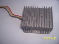
I have just ordered one of these $15 dc/dc converters for my next project, specifically to operate 12V relays from a 48V pack. It is only 8 amps, but should do the job with lots of room to spare. The nice thing about this one is it has wires to connect to. The last one I got had funny and odd connectors, but it is probably a better quality product.

http://www.partsforscooters.com/s.nl/it.A/id.3243/.f

Edit: This is the first one I got, which is working great in the Trike/Trailer:

http://endless-sphere.com/forums/viewtopic.php?f=7&t=2800
 
But I tun at 84v, and perhaps eventually 112v. Could I put two of those units in series and then parallel their outputs? To drive them with anything between 70v and 116v?

In the meantime, I'm using one of my 3-cell LiPo RC packs to drive my lights and the relay. However, it is far from an optimal solution. The discharge curve isn't too great for things that can't be driven below 10v. My LED buckpuck will operate with anywhere between 5v and 35v, but not my cheap floodlights or the relay. I found out the hard way that though the relay might work without my LEDs on, the voltage sag from just ~10w was enough to keep the relay from engaging. Thankfully, my friction brakes still worked well enough!
 
laz... wrote:

But I run at 84v, and perhaps eventually 112v.

Just a guess, but you probably charge your sub packs separately, so any unbalance caused by running things off one side of your battery pack would be rebalanced every time you charge, and hence cause no problems. I might be tempted with a setup like yours to run a critical item such as a brake relay off a dedicated converter running off an appropriate size (voltage) sub pack. Then something like your high power lights might be best running several in series to directly match a sub pack and thus not require any converter. Just thoughts. Good luck.
 
Well, everything that isn't running off of 84v run off of 12v. All my subpacks are 28v, so I guess I could easily get one of those units and run it off of two subpacks.
 
The scooter converter came today. I checked it out on the bench with a 48V pack and it delivered 11.3V according to my DVM. The red wire is input for 48V positive. The black wire is a common ground, i.e., goes to the 48V negative and is used as the negative on the 12V sub-system. The yellow wire is the 12V positive.
 

Attachments

  • 48V - 12V 04.jpg
    48V - 12V 04.jpg
    11.4 KB · Views: 912
Back
Top