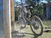
madmaxNZ's H4080 in a Giant DH Comp

madmaxNZ

10 mW
Joined
Mar 24, 2013
Messages
34
Location
New Zealand
Over the last year I've built up my first ebike:
Crystalyte 72V 50A controller (running at 100V max charge)
Cytlyte H4080 motor
24s3p 5aH LiPo (88.8V nominal 15aH)

I've done about 500Km on the bike. Mostly through forest tracks.
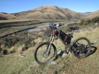
Ashley Headwater1.jpg
Ashley Headwater2.jpg
The poweris pretty impressive, and I managed to bruise my ribs in the first 5minutes of getting it going by pulling wheelies...I know it's not recommended for new batteries etc but that's where the "mad" comes in.
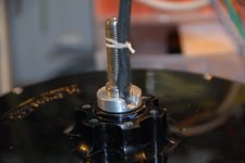
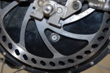
I quickly found that overheating was an issue on hils, so I went for the oil cooling option by tapping a 6mm thread in the side cover a little below the axel...drilling a breather hole thru the bolt and filling with INOX M3 oil up to the hole. This greatly improved cooling to a very acceptable level. The crystallyte motor came sealed well enough. I put some extra RTV sealant in the cable slot though.
DSC_0024 (2).jpg
 
I've had an issue with Crystalyte's motor phase wire insulation being crap!
It has recently either cracked causing a short or just softened under heat to the point of causing a short!
This in turn has taken out most of the FET's in my controller and also the driver circuits for the FET's.
melt 3.jpg
melt 1.jpg

Here is a pic from a fellow ev.geek.nz forum member from May last year. His Crystalyte HS3540 motor and controller wire insulation were found craking up. Lucky for him, was found before any damage to his controller.
Dave, I hope you are ok with me using your photo, but I think it's important to get the message out that these wires need upgraging.
motor-phase-wires-comp[1].jpg

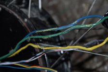
My H4080 motor wires are 12AWG and the insulation looks like a thin film of teflon, but it definately isn't teflon as I know it. The controller wires are 10AWG and they show no signs of overheating or cracking as yet.

Here's a not very profesional video clip of me testing the Crystalyte wire against real teflon wire:

http://www.youtube.com/watch?v=IYB2gnkEWYo

[youtube]IYB2gnkEWYo[/youtube]

The shorting happend during a hill climb, here is the senario:
All went well until the Hill section where admittedly I was pushing the limits when it all stopped. I was about 6Km up the valley. The motor's temp on the CA v3, only showed 81degC, so I thought I'd blown the fets in the controller; I went to go back downhill and the hub was braking magnetically like when the phase wires are shorted; I thought it was the controller causing the short, but after unplugging the motor from the controller, it was still "mag braking"...feckity feckin feck...I thought then that the windings were shorted and I was up for another motor. Pushing the 40Kg bike back along the 4WD track with "mag braking' was a slow affair, so I stashed the bike in some bushes and legged it back to the truck. Luckily the track gate was open and I could drive back to get the bike.

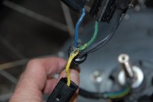
At home I found the "yellow" wire insulation split near the connector and the three wires melted togeather. Separating the wires freed up the "mag braking". The motor's windings showed no signs of overheating (makes sense since temp was only 81degC at the time), so I'm assuming this was a combination of shit insulation and me pushing the limits causing the wires to heat rapidly before the CA's set limit (85 to 90degC cut off) for motor temp.

Has anyone had similar issues with this wire or any correspondence re this from Crystalyte?
I need a new controller now.

Any suggestions or recommendations re a new controller for a power ebike?

I'm not anti crystalyte...they just need to sort their insulation out.
 
I've blown my 12 fet controller the same way you blew yours max. The wires melted together and shorted and blew the controller. The 12 guage wire as you knows rated to 200 degrease. Hill climbing anymore that 30 seconds where the motors pulling more that 30 amps over that period is more than enough to heat up these motors. I've ordered phase wire directly from Kenny at crystalyte. I'm going to try the 11 guage wire that's used in the 54series motors. Problem though it may not fit. When I hill climb I try to give the motor some assistance and keep amp below 20 this does help. I'd like to try different Teflon wire too but would like to try one that proven.
 
Clyte's phase wires usually have PVC, very thin insulation. I cover them with heat shrink and keep them short, splicing and soldering 8 ga wire on them few inches off the axle.
 
Damn those clyte engineers, didn't design a 1000w motor to handle 4000. :evil: Definitely re do the wires with as short as possible of the skinny.

But I have to say, in all the 9c motors I've heated up, I never saw that happen. I think the best thing would be to drop it to 18s or 20s. I saw exponentially more heat when I took the 9c motors to 110v max. It becomes a question of what you need, that much power or reliability.

Or order up a cromotor soon.

I have found a cheapie seatpost rack plus a scrap of anything flat and waterproof makes a dandy rear fender. Gives you a place to stash a drink, snack, or emergency tire repair kit. Often I just stick the controller on top of it too.

Oh, and really nice work building up that bike. I can't see the details of the battery box, but it looks very well done.
 
MadRhino said:
Clyte's phase wires usually have PVC, very thin insulation. I cover them with heat shrink and keep them short, splicing and soldering 8 ga wire on them few inches off the axle.
they have PVC China brand style.
I have worked with China brand wires on Chinese paper cutters and know them very well, the one in your pictures looks exactely like ones I was replacing with UL/CSA approved NAmerican wires. There are not even marked with any ratings or approvals.Those paper cutters could not be sold in NAmerica with not approved/not certified wires of shoddy quality so they had to be replaced.
so much for quality of China brand motors improving ,something opposite.
 
Looks great.

Any chance you could share some details and take a close-up shot of your battery enclosure please?
Also, have you encountered any problems with your oil filled motor or 'breathing' bolt?
 
Rodney64 said:
I've ordered phase wire directly from Kenny at crystalyte. I'm going to try the 11 guage wire that's used in the 54series motors. Problem though it may not fit. When I hill climb I try to give the motor some assistance and keep amp below 20 this does help. I'd like to try different Teflon wire too but would like to try one that proven.

Hi Rodney,
I hope Kenny looks after you and the wire is a better spec for your purpose. 11G may be pushing the fit, but there is always the 'Dremmel" option to carve more room.

I work in the Aircraft industry and have access to an offcut of some proper teflon Hi Temp 12AWG wire which will just fit...I hope; so I'll give it a try. I'll replace my new controller wires (when I decide on one) with the 10G Silicon stuff from Hobby King.
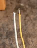
It measures 3.4mm diameter compared to about 2.7mm of the original Crystalyte wire (may be some heat shrinkageon the crystalyte wire I had to measure).
It is a Boeing spec "BMS13-58T1C1G12". The last two digits are the gauge.

DSC_0005 (2).JPG

I had a quick search on Google for a supplier under that number and a few come up. It was listed in our stores at US$2.50 per foot. Maybe a keen person could buy a small quantity for distribution to the needy. The only bad thing about it, is that is hard to solder. You need to use flux paste and plenty of heat to 'tin' the wires; once tinned you're away and can solder as normal. Crimping is the way to go, and this is the common method for most Aircraft Harnesses.

This wire can handle in way in excess of 200degC...I'll see if I can set up a better video at work with a High temp probe and see how much it can handle without melting. This is the grey wire in my crappy video above, which took the heat gun in its stride, while the "quazi teflon" (PTFE I think) melted.
 
dogman said:
Damn those clyte engineers, didn't design a 1000w motor to handle 4000. :evil: Definitely re do the wires with as short as possible of the skinny.

But I have to say, in all the 9c motors I've heated up, I never saw that happen. I think the best thing would be to drop it to 18s or 20s. I saw exponentially more heat when I took the 9c motors to 110v max. It becomes a question of what you need, that much power or reliability.

Or order up a cromotor soon.

I have found a cheapie seatpost rack plus a scrap of anything flat and waterproof makes a dandy rear fender. Gives you a place to stash a drink, snack, or emergency tire repair kit. Often I just stick the controller on top of it too.

Oh, and really nice work building up that bike. I can't see the details of the battery box, but it looks very well done.


Hi Dogman,

4Kw??….Yes those Crystallyte engineers do have a lot to answer for, of course it should perform like a Honda XR500 trail bike and only weigh 40Kg :wink: ….well to confess, the CA max current was 57A and I think Vmin was about 90V..so circa 5Kw +.
I would have thought the 50A controller should have limited this somehow? I normally have the CA set to 50A 5Kw max, but forgot that I changed it in an experiment to 60A 6Kw max and forgot to set it back. Still the motor temp only got up to 81degC on this one particularly steep bit of hill and think it was ultimately an insulation failure (driven by a little mindless madness).

I’ve considered the Cromotor, but am put off by any extra weight. I find my 40Kg bike enough when lifting over fences and gates. Maybe the Crown could be an option once the “stuttering” glitches are ironed out.
Re the pack voltage: so to get the same range as my 24s (88.8V nom) 15aH pack (1332WH) with a 20s pack (74Vnom), would I need an 18aH (1332WH) to 20aH (1480WH) capacity? :?:

I’ll post some detail of the Battery box and a couple of other bits and pieces below. The battery box is an easy option which I thought was pretty cool until I spotted Timma2500’s builds:
http://www.endless-sphere.com/forums/viewtopic.php?f=6&t=34719&hilit=Timma2500+%C2%BB

Thanks for the carrier/mudguard advice.
I Need to look at new controller options. I’ve emailed Kenny (which one, I’m not sure) regarding the wire situation and controller options, but so far no reply.
 
shorza said:
Looks great.

Any chance you could share some details and take a close-up shot of your battery enclosure please?
Also, have you encountered any problems with your oil filled motor or 'breathing' bolt?

Hi,
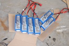
I went for Turnigy 6s 5aH packs and the Turnigy 400W 4x6s charger from Hobby King.

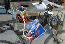
Battery Box Mk1 was two food containers which proved the ebike concept for me. They only held 24s 2p (10aH)...I wanted more range. Charging was a pain with no proper balance or charge plugs.

View attachment 17
DSC_0015 (3).jpg

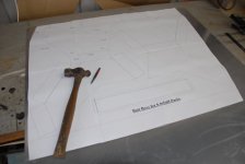
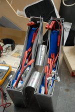
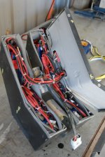
Mk2 Battery box was made to fit 24s 3p (15aH). I did a cardboard mock-up and a drawing using publisher. I then printed 1:1 for transfer onto a sheet of 1.2mm commercial grade aluminium. I can't upload the publisher file of this, but will scan as a jpg if anyone wants it. I used a jig saw to cut the pattern out which worked well with minimal filing required. I bent the box's up at work using a Mag Folder which is great for the tricky corners a conventional folder cant do. A coleague welded it for a bag of mixed nuts...good deal and good welding.

DSC_0007m (5).jpg
DSC_0009 (5).jpg
View attachment 14
DSC_0004 (5).jpg
Inside.JPG

The two bins are held togeather with two straps; I used flat head screw filed flatter inside and trimmed back/filed the excess threads from the frame side.
The bins slide down the frame and are captured in place by a bent piece of stainless steel held in place by a band clamp.

View attachment 13

Currently I’ve got a strap and tape around the box and controller for security. I have since used Velcro for the controller which works fine (quick release). In future the Box will be held underneath by a single quick release clamp which will sweeze the box together on the frame. This setup allows quick removal of the battery box from the frame (in case I have to throw it into a river one day to put out the fire).

I’ve wired it for a 8 pin plug to separate the pack into 4 x 6s and a D connector for the balance wires. The plug is a waterproof bayonet type (aircraft stuff) and has 12G pins. The pack is connected in series with a “Run Plug” that links the four 6s packs in series (24s); when removed the charger plugs in and deals with each 6s pack separately.

DSC_0015 (5).jpg
View attachment 10
View attachment 9
View attachment 8

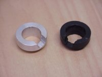
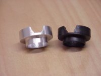
The oil cooling works well. It is a must for any sort of hill climbing. I do extended climbs drawing 20 to 30amps with the oil cooling. Where I would stop 5-10 times before...I only stop once. I set my temp cutoff for 85 degC My H4080 came with a plastic insert which protects the wires from the lip seal; I understand the earlier HS motors didn’t have this and cut the wires.
A friend turn up an aluminium insert for better wear resistance. It is surprising that the rubber seal has still managed to put wear marks in it after 500Km. I have a drawing for this too if anyone wants it.

MVC-289X.jpg
MVC-290X.JPG
DSC_00080164.jpg

Initially I did not have the breather hole and oil managed to go up my motor wire sleeving and come out at the connector. It also came out the axel slot. I put RTV sealant around the side covers as a gasket and had no leaks there. The small breather hole in the bolt completely solved this problem...amazing. I do get a very small amount of seep out of the breather which may get on to my rear disc brake, so I plan drill another breather hole on the freewheel side and just have a normal bolt for topping up the oil on the disc side.

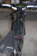
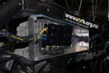
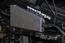
While I'm on a roll. Here's the wee box I bent up to keep the mud and crap off of the motor/hall/temp probe connectors. Works rally well ans seems to keep water out too. It fits snugly in the frame and is held there with a bead of RTV.
Since last picture: I've stuck fake carbon fibre on the cover which looks ok and it is held on with four screws.

View attachment 3
DSC_0007 (2).jpg
DSC_0010 (2).jpg
 
Hi Temp wire insulation BMS13-58T1C1Gxx (xx = gauge required): Solder is the weakest link.

http://www.youtube.com/watch?v=BakJBCH44h4

[youtube]BakJBCH44h4[/youtube]

The video shows the solder melting at around 147degC: we know solder melts around 300degC. The solder was in the immediate heating zone and got up to temp quickly; there was a big lag with the temp probe getting up to temp: I most likely had it set too far back from the air stream again, but it still proves the point that the BMS insulation can handle heaps of heat. As you can see, I left the heat on for an extended time and we got up to around 450degC. There was no discolouration or deformation of the wire…I didn’t want to touch it to see if it had softened. At that temperature any soldered joints are going to fail, so wire insulation is not going to be your weakest link.
Someone in the US may be able to track down a local supplier for this wire. As mentioned previously, this wire is easier to crimp than solder…if soldering you need to first tin it using flux paste and plenty of heat; once tinned you’re away as normal.
 
pendragon8000 said:
nice work with the charger plugs. is the controller powered via that 8 pin plug? and how wide is the box? looks like 15cm? i guess you would be used to it after a few minuets of riding.

G'day, the plug forms the series circuit for the batteries, so yes. The pins are 12G with 10G link wires. I've run 50A thru these pins and get about a 0.8V drop thru the 8 pins. I would have liked to use 10G pins, but couldn't find a decent sized (small & compact) connector to suit. It was a bit of an experiment to use only 12G pins, but it seems to work. Powerwerx sell an anderson system http://www.powerwerx.com/powerpole-accessories/ but it's pretty wide and deep for my box. The other option would have been to make a custom plug with larger contacts.
The receptacle on the box is a Flange mount MS24264R18B8PN and the two cable Mount Plugs are MS24266R18B8S (run plug and charger plug). The contacts are crimped...not soldered...see above video.

If you look closely you see the Run Plug just plugs in to form the series link, the two wire anderson connector is wired inside the box and connects to the controller as standard; the run plug could double as a 'key' of sorts while you went into the pub for a beer.

The box is 175mm wide and doesn't bother me when I pedal (if I'm feeling keen). It is as simple as I could make it for ease of removal etc. The model DH comp I have has bugger all room for batteries in the triangle. I plan to copy Timma2500' Specialised Big Hit frame in the near future; I've already got a frame lined up.
 
MadRhino said:
Clyte's phase wires usually have PVC, very thin insulation. I cover them with heat shrink and keep them short, splicing and soldering 8 ga wire on them few inches off the axle.

Good idea re heat sinking with the heavier cable. I'm a bit short on the 12G scrap pieces so will need to do some splicing anyway.

Cheers Max
 
shorza said:
Great, thanks for the big write-up. I may steal your breather bolt design.

Hey, I go tthe idea off a forum: ev.geek.co.nz. You will no doubt add your own twist on it. Just note that it may be better to put the hole on the freewheel side up as close to the axel as possible (just a small hole, no bolt needed) and put the bolt on the disc side as a 'fill hole' at the height for the desired oil level. It's a simple way to go and if you don't like it, or need more cooling, then you only have one small tapped hole in your motor. Pretty easy to fill up. You shouldn't be disappointed though. I do plenty of hilly shingle roads (not real steep like the one that fried my wires but some long moderate runs) and it is a pretty good cooling method for the amount of effort required to give it a go.
Ultimately a water cooling system is the way for max cooling: check out http://www.endless-sphere.com/forums/viewtopic.php?f=6&t=26029
A little more work, but imagine the power you can stick to that hub :twisted:
 
madmaxNZ said:
; the run plug could double as a 'key' of sorts while you went into the pub for a beer.
YES! Beer switch :)
madmaxNZ said:
The box is 175mm wide and doesn't bother me when I pedal (if I'm feeling keen). It is as simple as I could make it for ease of removal etc. The model DH comp I have has bugger all room for batteries in the triangle. I plan to copy Timma2500' Specialised Big Hit frame in the near future; I've already got a frame lined up.
Check my second build if you haven't..
its currently out of action because of structural failure "FAIL" anyway this weekend i intend on reinforcing it with triangles. Please make sure your design is more than enough to cope with angular stresses. Note, I tryed something different and had a bottom opening battery box that was the cause of my issue.
 
I've got my motor back together with some high temp BMS spec 12 gauge wire. Kiwi told me that the wire melt is a problem he has seen with the Anderson connectors heating up and transferring the heat to the wires; this looks to be true given the meltdown happened at the point where the wires come together close to the connector and the heat of the connector when I unplugged it.
I had the Anderson PP75 (apparently good for 120A) on my motor.

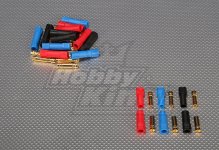
I want to use different connectors this time and are considering the XT150 Connectors w/ 6mm Gold Connectors from Hobby King ["XT50's are big 6mm sprung gold connectors that have a large contact area, making them great for high power applications up to 250A!"]

Has anyone tried these or have any better suggestions?
XT150.jpg
 
madmaxNZ said:
I've got my motor back together with some high temp BMS spec 12 gauge wire. Kiwi told me that the wire melt is a problem he has seen with the Anderson connectors heating up and transferring the heat to the wires; this looks to be true given the meltdown happened at the point where the wires come together close to the connector and the heat of the connector when I unplugged it.
I had the Anderson PP75 (apparently good for 120A) on my motor.

I want to use different connectors this time and are considering the XT150 Connectors w/ 6mm Gold Connectors from Hobby King ["XT50's are big 6mm sprung gold connectors that have a large contact area, making them great for high power applications up to 250A!"]

Has anyone tried these or have any better suggestions?


Yes I'm using XT150,s. so far so good. I'm still using Anderson's to connect the battery. Good to here that the 12 gauge aircraft wires working so will look on eBay.
 
It's an odd size (12G) for us at work and I was lucky to get the last feww feet of a roll; we have plenty of 20G & 14G.
The O.D. is a bit more than the original wire, so I had to linnish out the slot to get it in; it is still a really tight fit.
I'll post some more photos of the repair shortly.
My new controller (72V 50A) from Kenny should be here today; the shipping speed was excellent: ordered last Wednesday and it arrived out of Auckland (N.Z.) customs on Friday morning (2 days); it sat there over the weekend and was in Christchurch heading my way Monday (yesterday). All in all, Kenny got it in the mail using TNT very quickly, so all credit to him.
The XT150's were ordered a couple of weeks ago from H.K. and I see have arrived in Auckland, so should be here by the weekend.

To get say 10G wire thru the slot... has anyone tried using the axel as one of the conductors, so you only need to run two wires thru the slot??
 
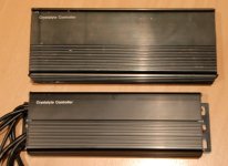
Just got my new controller from Crystalyte (72V 50A). The package is a lot more compact than my old one as it fits closer around the circuit board. Nice. :D

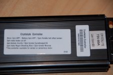
The new one has re-gen and no 3-speed switch: bugger :cry: , I like the 3-speed as it controls the power at low speed better. I should have been much more specific and not assumed it would be the same...especially since on the first quote Kenny had specified the AMP display plug - not the CA DP!

Here's some questions: :?:
1. If I find the correct pads on the circuit-board and connect the plug for a 3-speed switch, will it work?
2. With no 3 speed switch, what is the power output of the controller: High, Medium, or Low? (My old one was medium with no connection)
3. What is the maximum output voltage of the re-gen circuit. Will 24s Fry the re-gen circuit?
4. Is it ok to use re-gen with LiPo batteries that do not have a BMS?

New to Old Controller Size.JPG
New controller Pin-outs.JPG
 
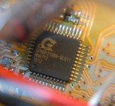
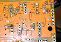
The New Crystalyte Controller, 72V 50A, has a new circuit board layout and new microprocessor; the 3-speed switch and programming pads are there:

New Chip.JPG
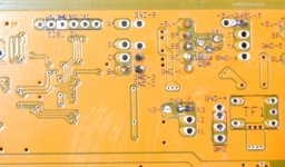
new program pads.JPG
New x1 x2 gnd8.JPG

I've connected a plug to the X1, X2 & Gnd pads for the 3-speed switch (same pads as my old controller), but don't expect the switch to work [Re-gen is using X3]; I'd be surprised if it did since no connection would be "medium" power and the controller would have not been putting out its full potential.
A parameter designer will need to be fired up to try and get the speeds setup correctly if one exists for this chip.
The pads for connecting the parameter designer look the same and I've soldered in the cable/plug for future connection, but I'm not risking using the old designer and killing another controller until I know what the story with this different uP is: can anyone help with information here.

:?: Has anyone used "a" parameter designer on this new chip? :?:

My email to Kenny with the questions in the last post above, had the following reply:

Hi Max,
Thanks for your mail.
The 72V 50A controller's circuit-board for CA-display. It is not available with 3 speed switch. ( The one you have received 0
The controller's circuit-board for Crystalyte APM display available for 3 speed.
It is okay for re-gen without the battery BMS.
Feel free mail me if you have more questions.
Kind Regards
Kenny


My old controller had no re-gen, but it did have the CA-DP and a 3Sp Switch. I've emailed him again to clarify why the 3Sp Sw is no longer available and to clarify that this controller is suitable for both sensored and sensorless motors...a handy feature if you are out in the boonies and loose a hall sensor.
 
Back
Top