Magura Throttle 3 wire...

unclejemima

100 W
Joined
Jun 10, 2012
Messages
251
Location
Western Canada
I'm confused as to how much "customizing" is requried with the Magura throttles?

My bike has a 3 wire half throttle, but its very un-responsive...usually takes 1/4 throttle before there is any response from the motor.

I want to replace it with a Magura 3 wire full throttle, but I'm confused if it is a simple plug and play or if there is modifying of the of the throttle to make it work?
 
throttle%2520adapter%25200.0.png


http://www.endless-sphere.com/forums/viewtopic.php?f=2&t=54876

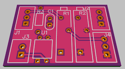
Adding a variable resistor to the top and bottom ends of the Magura allows you to "tune" it and adjust the deadband out. There is a schematic in the thread for the board above. It is simple enough so you don't need a PC board. The board offers some other features as well as a convenient platform for mounting the variable resistors.
 
StudEbiker said:
no dead spots immediate and even response. Very simple from what I remember.

Cool. This is what I'm looking for.

What wire did you put the 1.5K resistor on? Can you confirm if the above link is the same product you purchased?
 
Thanks. I checked the above link...

I thought Magura was supposed to be "top quality" when it appears its common to have to dis-assemble it and correct the gears inside...? Are these made in China or Europe? (I thought Magura was from Europe)

Question. If someone makes a setup with resistors like the provided link, will it work on any ebike, or does it have to be customized for each motor/application?
 
unclejemima said:
Thanks. I checked the above link...

I thought Magura was supposed to be "top quality" when it appears its common to have to dis-assemble it and correct the gears inside...? Are these made in China or Europe? (I thought Magura was from Europe)

Question. If someone makes a setup with resistors like the provided link, will it work on any ebike, or does it have to be customized for each motor/application?

HAL throttle works with 1.2 volts to 4v at WOT. without the resistors the magura will provide 0-5 volts. So you end up with dead space. It will work on any controller with a HAL throttle. Having variable resistors will enable you to fine tune it even more so.

Wishes
 
Wishes said:
HAL throttle works with 1.2 volts to 4v at WOT. without the resistors the magura will provide 0-5 volts. So you end up with dead space. It will work on any controller with a HAL throttle. Having variable resistors will enable you to fine tune it even more so.

Ok. Anyone know if the Bafang BBS-02 has hall throttle sensor?
 
unclejemima said:
Wishes said:
HAL throttle works with 1.2 volts to 4v at WOT. without the resistors the magura will provide 0-5 volts. So you end up with dead space. It will work on any controller with a HAL throttle. Having variable resistors will enable you to fine tune it even more so.

Ok. Anyone know if the Bafang BBS-02 has hall throttle sensor?

Yup I believe it is.

Wishes
 
I've confirmed the Bafang has a Hall sensor. The controller reads throttle input as 1.2 to 3.5V.

So, if I used a 1.5v resistor, would the throttle not start reading until 1.5V then...effectively missing the first 0.3v of the throttle range?

So, if I'm understanding this correctly, I need a resistor to bring up the voltage from 0 to 1.2, then reduce the top end of the throttle from 5.0 to 3.5.

So would I not need a 1.2V resistor on the bottom and a 1.5V resistor on the top end?

Thanks...and sorry for the NOOB questions!
 
unclejemima said:
the controller reads throttle input as 1.2 to 3.5V.
...
So, if I'm understanding this correctly, I need a resistor to bring up the voltage from 0 to 1.2, then reduce the top end of the throttle from 5.0 to 3.5.
Exactly - you need both resistors to properly bracket the Magura range - a single resistor will leave you with a 'dead zone' at the other end.

Here's the rub: Variations in components in the controller and throttle can lead to different throttle resistance and different controller input range. As far as top and bottom 'dead zones' are concerned you can detect a difference of only .1v in throttle rotation, so to get the best possible throttle range, the resistors need to be adjusted for the particular throttle and controller - not just the general brand and model. This is why many folks use trimpots instead of fixed resistors - as in the little PCB earlier in the thread.

That said, you *can* use fixed resistors, but you will do better if you make a few measurements:
  • the actual Magura resistance
    --Just measure this with a meter (mine have been around 5.5K)

  • the actual min/max controller voltages
    --Put the bike on a stand and hook up the Magura without resistors. Advance the throttle and note the throttle voltages at which
    • the wheel just begins to turn (min) and
    • spins no faster with added throttle (max).
    You can get these by probing the back of the throttle connector with a meter.
You will typically want to increase the throttle min/max about 0.1v beyond what the controller expects to ensure there is no creep at ZERO throttle and that you can actually achieve WOT - even with a little drift in parts values. For instance, in your case of (min, max) = (1.2v, 3.5v) you would want to use a thorttle range of (1.1v, 3.6v).

Here's a little spreadsheet that will do the calculation for you - it works in Excel or Apache Open Office (free). Plug in the stuff in the green cells and it will give you the resistances. Plug in the actual standard value resistors you want to use and it will calculate back the actual voltage range you will get.

View attachment MaguraThrottleResistorCalculator2.xls
I don't know what your Magura resistance is or the actual controller range, but...
Here are two runs assuming 5K and 5.5K for the Magura. I used the 'claimed' controller voltage range and jacked it open a bit as mentioned above. Looks like 2.2K and 2.7K resistors will work fine if your Magura is 5K and okay even if it's 5.5K.
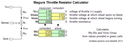
maguraCalc_5.0K.pngView attachment 1
Here's a last run using resistors of 2.4K and 3.0K if your Magura is 5.5K - somewhat better fit to the range.
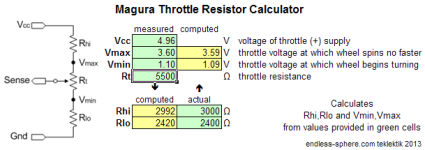
maguraCalc_5.5K.png
So - if you don't want to measure things, you might want to buy all four values and tinker a bit....
 
unclejemima said:
Can anyone post a ebay link of the resistors I would need (variable or fixed)
A couple of 5K multi-turn trimpots would work fine. The long thin kind can actually be heat-shrinked to the the throttle cable in a relatively straight area. You only need to set them once....

Search eBay: 5K trimpot 10 20 multi turn

Or use some carbon film resistors from radio Shack or eBay. You might find a cheap assortment that has the values you need (or that can be seriesed up the proper values. The power is negligible so any low wattage is fine (e.g. 1/8W) but if you are going to mount them in-line then a minimum of 1/4W will get you thicker leads for strength.

Search eBay: 5% resistor carbon film
 
teklektik, So if I go for this style...

http://www.ebay.com/itm/10-LOT-BOUR...455?pt=LH_DefaultDomain_0&hash=item27cd70a667

...is this the long slender ones you are talking about?

The magura throttle has 3 wires. There is also 3 wire taps that come out of the resistor. I will need 2 variable resistors. Again, NOOB question...what wires of the Magura do I hook up to the resistors to, and why do the resistors have 3 wires?

Thank you!!!
 
unclejemima said:
teklektik, So if I go for this style...

http://www.ebay.com/itm/10-LOT-BOUR...455?pt=LH_DefaultDomain_0&hash=item27cd70a667

...is this the long slender ones you are talking about?

The magura throttle has 3 wires. There is also 3 wire taps that come out of the resistor. I will need 2 variable resistors. Again, NOOB question...what wires of the Magura do I hook up to the resistors to, and why do the resistors have 3 wires?

Thank you!!!


See this post.

http://endless-sphere.com/forums/viewtopic.php?f=28&t=46891#p686535
 
unclejemima said:
teklektik, So if I go for this style...

http://www.ebay.com/itm/10-LOT-BOUR...455?pt=LH_DefaultDomain_0&hash=item27cd70a667

...is this the long slender ones you are talking about?
Ya - that's the proper style but the resistance is wrong - 10K instead of 5K. Fiddle with the eBay search parameters a bit and you might find more options (e.g. some sellers let you specify a value so leaving out '5K' might help).

unclejemima said:
what wires of the Magura do I hook up to the resistors to?
For the Magura:
  • blu - WOT end of resistance
  • brn - wiper
  • blk - ZERO end of resistance
unclejemima said:
why do the resistors have 3 wires?
The trimpots have a connection at each end of the resistive element and one for the wiper that gives variable resistance - much like the Magura connections. When wiring a pot as a simple variable resistor, you usually tie the wiper to one end so any contact bounce cannot deliver a resistance greater than the max resitance of the pot (i.e no 'open air' or no-connection situation). In this case that's not strictly necessary, but why not? :D
 
Ok. I missed the 10K thing. I don't mind these ones...

http://www.ebay.com/itm/10-PCS-3296...534?pt=LH_DefaultDomain_0&hash=item461bbfa66e
or
http://www.ebay.com/itm/5K-Ohm-Sing...609?pt=LH_DefaultDomain_0&hash=item461b952fa1

Is one style better than the others??? I like option 2 only because it have beefier looking connections and a much larger adjustment knob. What do you guys think?

This seller has the size that was suggested with the tall and slender (blue) in 5k. Could I also purchase a 2K for the bottom end, as I know it will be less than 2k for zero throttle, or is it best to stick with the same for both?
http://www.ebay.com/itm/6ea-Trimpot...426?pt=LH_DefaultDomain_0&hash=item4ad0f0caf2

Then, once I find my setting for resistance, then I would epoxy the knob so it cant move. Is this a good idea? Would it need adjustment down the road?

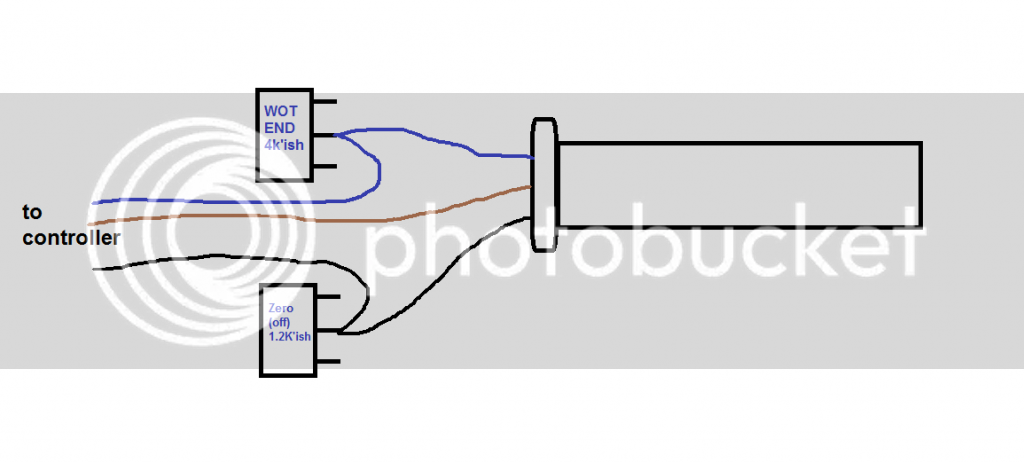
And, no thread would be complete without a paint schematic.

Like so?
 
No, your schematic is all wrong :)
Your pots are not used at all in that picture, the wire runs straight back to the controller, that won't accomplish anything.
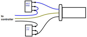
You need to run you "ground" and "high" wires through your resistors, like the picture posted here:
http://endless-sphere.com/forums/viewtopic.php?f=3&t=49699#p734583

Hope I made sense, basicly just connecting one of the pins on the pots wont give the connection any change in resistense.
 
You need to hook things up like this:

UJ-throttle.png
You can choose any style of pot that you wish - it's largely a mounting consideration - except that multi-turn pots are much easier to adjust and hold their settings in spite of vibration. With multi-turn pots there is no upside to getting into epoxy - leave them alone and you will be in good shape if your next controller has a different range. Actually, the single turn pot that you saw is much more fragile than the multi-turn because of the open mechanical parts and mounting vs fully-enclosed elements with potted wires.

Your lower resistor range is not quite right. The calculated fixed resistor values above put you low resistor at 2.2-2.4K and the upper at 2.7-3.0K. Ideally you want the target value in the middle 50-60% of the pot so this looks like a couple of 5K pots. With a 10 or 20 turn pot you can hit any of these value - (including something in the 1.5K range for the more conventional controller input range - your range is a little atypical which is why other folks used 1.5K resistors).

Check the link in the eBay ad for that vendor with 3 pot styles - I don't think he has all resistances in all styles....
 
Thanks teklektik and bjosta.

teklektik, your paint drawing looks much better than mine :)

In the thread listed (http://i1191.photobucket.com/albums/z469/Denisesewa/001-24.jpg it looks like he did not hook up the wiper on the resistors at all.

I'm going to hook it up exactly as teklektik illustrated.

And good to know on the trimpot adjustment. I'll try to get at least 10 turn model.

I'll let you know how I made out!

Thanks!!!
 
Back
Top