
You are using an out of date browser. It may not display this or other websites correctly.
You should upgrade or use an alternative browser.
You should upgrade or use an alternative browser.
Can a throttle be hooked up to this IKEA e-bike?
- Thread starter BlueSwede
- Start date
t3sla
10 kW
Standard lsdzs controller, the bigger white cable is USB used for new firmware. The other one not sure. Can you take photo of the cable colors?
Hello... my first post. ")
I just purchased an IKEA pedelec called FOLKVÄNLIG and I'm wondering if it's possible to install a throttle to it so that I don't have to pedal?
This is what the controller looks like and as you can see there are two unused connectors.
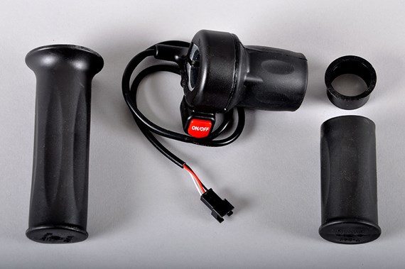
Do you think this throttle would work?
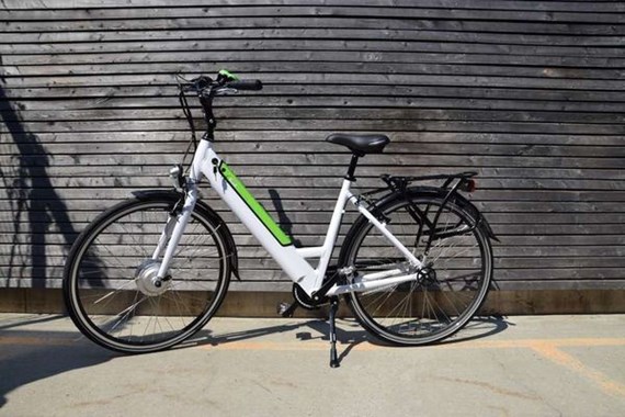
This is what the bike looks like by the way...
I just purchased an IKEA pedelec called FOLKVÄNLIG and I'm wondering if it's possible to install a throttle to it so that I don't have to pedal?
This is what the controller looks like and as you can see there are two unused connectors.
Do you think this throttle would work?
This is what the bike looks like by the way...
Thanks for the USB info... could this be used maybe to remove the 25 km/h restriction?t3sla said:Standard lsdzs controller, the bigger white cable is USB used for new firmware. The other one not sure. Can you take photo of the cable colors?
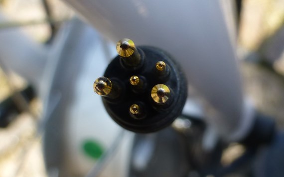
These are the colours of the other connector. Red, Black, Purple...

...and here's an overview of all the other cables.

Brgds... /BlueSwede
Sorry but I just realized I posted this in the wrong section 
I copied it over to the E-Bike section over here... http://www.endless-sphere.com/forums/viewtopic.php?f=3&t=63245
Maybe a moderator can delete the old thread?
Brgds... /BlueSwede
I copied it over to the E-Bike section over here... http://www.endless-sphere.com/forums/viewtopic.php?f=3&t=63245
Maybe a moderator can delete the old thread?
Brgds... /BlueSwede
MadRhino
100 GW
You could probably use a throttle plugged on the pedelec connector, for the controller is most likely to be responding to the same signal voltage range as a hall effect throttle. You can test the voltage change on the pedelec sensor to be sure, or you could just try plugging the throttle and see if it works.
I'm not familiar with how the pedelec system works... I thought that if the sensor detects movement it will move the motor at the speed selected in the display. Didn't think the pedelec signal controlled the speed at all (more like a on/off switch) but maybe I've misunderstood the workings of the "pedelec signal".MadRhino said:You could probably use a throttle plugged on the pedelec connector, for the controller is most likely to be responding to the same signal voltage range as a hall effect throttle. You can test the voltage change on the pedelec sensor to be sure, or you could just try plugging the throttle and see if it works.
I measured the voltage on the unidentified connector and it's like this...
Black 0V
Red 38,5V
Purple 0,2V
Is that normal for a throttle connector or should it be 5V?
Brgds... /BlueSwede
dnmun
1 PW
the throttle lead from the controller will have ground and 5V and the return signal line will have no voltage from the controller.
the wire there with the 38V is to power the led that indicates power is on for the battery meter attachment.
if you wanna open the controller there may be a label printed on the pcb to attach the leads for the throttle wire or the label will indicate where the throttle signal lead returns.
the wire there with the 38V is to power the led that indicates power is on for the battery meter attachment.
if you wanna open the controller there may be a label printed on the pcb to attach the leads for the throttle wire or the label will indicate where the throttle signal lead returns.
Ok, so that unidentified connector is not a throttle connector then?
Is it then possible to disconnect the pedelec connector and connect it to some kind of throttle instead? Even if it's not an adjustable throttle but merely an on/off switch for the motor it would still be better than nothing.
Brgds... /BlueSwede
Is it then possible to disconnect the pedelec connector and connect it to some kind of throttle instead? Even if it's not an adjustable throttle but merely an on/off switch for the motor it would still be better than nothing.
Brgds... /BlueSwede
dnmun
1 PW
i doubt it. i imagine the pedelec sensor just has some hall sensor inputs from the magnets on the crank ring thingy to sustain a voltage on a capacitor that is used by the controller as the input for the pwm the controller uses to control output power. you may find a label on the controller pcb for the throttle inputs though. or we can show you where to wire it in.
999zip999
100 TW
Welcome to E.S. BlueSwede nice fine please keep us posted on how this new model works out.
As per E.S. we want to know what's inside. Looking for three wires plug with 5v. Maybe four if one is 36v for battery gauge.
As per E.S. we want to know what's inside. Looking for three wires plug with 5v. Maybe four if one is 36v for battery gauge.
wesnewell
100 GW
Your controller has a throttle input. It's stated right on the label. All you have to do is find it. Normally, they are 3 wires. +5V, ground, and return sense wire. I'd guess it the white 3 wire connector. Measure voltage across the red and black and see if you get about 5V. If you do, they use a resistor from the positive side to the purple wire and see if the motor turns. Make sure the wheel is not on the ground when you do this for obvious reasons. If that isn't it, it may not have been wired out of the controller, or it may be another connector.
dnmun said:i doubt it. i imagine the pedelec sensor just has some hall sensor inputs from the magnets on the crank ring thingy to sustain a voltage on a capacitor that is used by the controller as the input for the pwm the controller uses to control output power. you may find a label on the controller pcb for the throttle inputs though. or we can show you where to wire it in.
I lifted up the bike a little so that I could have a look at the "pedelec" cable. Seems to me like there are pulses instead of a voltage that controls the speed. Have a look:
[youtube]i9py1075O7E[/youtube]
Brgds... /BlueSwede
dnmun
1 PW
the magnets on the chain ring go by the hall sensor and switch it on and off and that allows charge and voltage to pile up on the capacitor that feeds the pedelec signal to the controller. that is my impression of how the pedelec works.
Hmm... OK. You asked me to open the controller and have a look. Any clues after looking at these pictures?
Warning... the images are quite large (5 Mb each) as I didn't want to reduce them in size and lose detail.
http://oi60.tinypic.com/nffsjq.jpg
http://oi62.tinypic.com/14w6hvl.jpg
So my goal here if possible is to disable the pedal sensor and use a twist throttle instead.
How does a "hall effect throttle" work? Would that be possible to put in the pedal connector instead?
http://www.ebay.co.uk/itm/Ebike-Throttle-Kit-Twist-Grip-Hall-sensor-type-incl-push-switch-UK-Stock-/151408418031?pt=UK_sportsleisure_cycling_bikeparts_SR&hash=item2340a51cef
Brgds... /BlueSwede
dnmun
1 PW
did you see any labels that said throttle?
if you unplug those white plugs and take a vga size picture it will download here. we do not need 5meg pictures anyway.
if you unplug those white plugs and take a vga size picture it will download here. we do not need 5meg pictures anyway.

t3sla
10 kW
Interesting, they have used the FOC model, the old version struggled with getting the initial position of the motor, so they disabled the 6km function
I have no idea what that means?t3sla said:Interesting, they have used the FOC model, the old version struggled with getting the initial position of the motor, so they disabled the 6km function
I've read about pedelecs that have twist or thumb throttles that work up till 6km/h and that it's usually a matter of adding or removing a jumper to disable the 6km/h limit (if I press and hold the minus button on my Ikea-bike the wheel starts to turn slowly, maybe 6km/h).
Not sure what all this means in the case of the IKEA FOLKVÄNLIG though. It would be wonderful to be able to add a throttle to it.
These are all the connectors coming out from the controller. Maybe the wires in the unused connector could be moved to other pins on the pcb where they can be used as a throttle?

Brgds... /BlueSwede
Normally throttle wires are red black and white. You have a red black and white connected to the red black and yellow. Where do the red black and white come from? What are you calling a "resolver". I've never heard of that before. Is it a motor speed sensor?
Edit: Having looked at it again and thought a bit more, I'd say that the black red and white must be a motor speed sensor. You could try unplugging it to see if it releases the speed limit. I believe that you need to wire an additional connector to the controller pcb to use a throttle. At the bottom of the white internal connector are four unused pins. Three of them are marked "GND", "VSP5v" and "SP". "SP" is almost certainly the throttle signal and the other two, the supply.
You could test if it works by shorting "SP" to "VSP5V". If the motor goes at full speed, that's it.
d8veh said:Normally throttle wires are red black and white. You have a red black and white connected to the red black and yellow. Where do the red black and white come from? What are you calling a "resolver". I've never heard of that before. Is it a motor speed sensor?
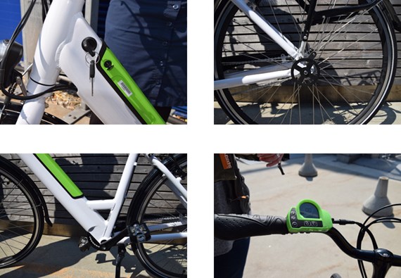
The red black white goes to the motor together with the three power cables through this connector on the front wheel fork.
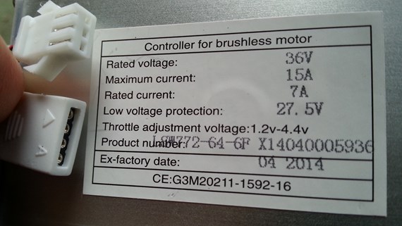
This is the only text on the motor.

The motor enclosure looks like this.

And finally my only mod so far... I've added a front basket! :wink:

Brgds... /BlueSwede
Guess what... it DID remove the speed limit!! Of course the odometer on the display doesn't work with the speed sensor unplugged. Wonder if there are other ways to disable the speed limit?d8veh said:Edit: Having looked at it again and thought a bit more, I'd say that the black red and white must be a motor speed sensor. You could try unplugging it to see if it releases the speed limit.
Anyways... now I really need a throttle because I'll never be able to pedal at this higher speed!
I tried shorting SP to VSP5V and it DOES move the motor... but only for a short fraction of a second and then it stops.d8veh said:You could test if it works by shorting "SP" to "VSP5V". If the motor goes at full speed, that's it.
We're really getting close here... thanks for helping!
Could I wire a potentiometer to "GND", "VSP5v" and "SP" or do I need this Hall type throttle?
Brgds... /BlueSwede
dnmun
1 PW
if you can, put 3V between grd and Sp to see if the motor will run. no need to short the 5V to Sp but if you do it has to be less than 5V so you would have to make a voltage divider to get the throttle signal below about 4.4V.
see if there is a 3 wire connection in the plug on the other side or if it is missing altogether.
see if there is a 3 wire connection in the plug on the other side or if it is missing altogether.
Similar threads
- Replies
- 7
- Views
- 287
- Replies
- 20
- Views
- 574
- Replies
- 6
- Views
- 200