09 bottle battery

Joined
Mar 14, 2013
Messages
2,282
Location
The not so UK
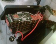
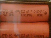
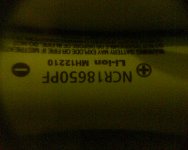
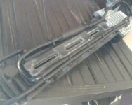
I just got two of these. Both types of 48v pack with both standard and internal controller mounting hardware.

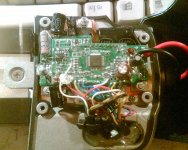
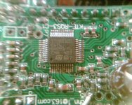
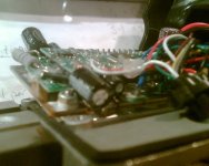
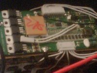
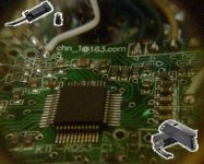
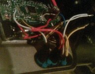
I'm going to open them up to consider raising the 20A bms limit and 20A controller limit.

Has this been done before? I would be much happier reading someone else's thread than starting from scratch.

Are there any pictures in particular that people would like?


The 48v 11.6ah battery weighs 3249g
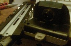
The base with controller weighs 386g
A key weights 8g
Total 3643g

The 48v 10ah battery weighs 3209g
The base without a controller weighs 277g
With a key, that's 3494g

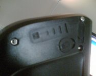
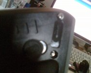
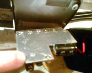
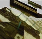
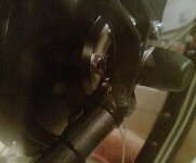
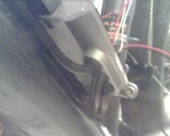
Looking them over, I see the same micro fractures on each. Just about every hole or indentation has a fracture leading from it. Likely from manufacture.
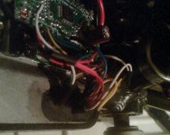
 
Pics of the damage would be good, if you can get clear ones. Might tell us something about how it was handled/made and whether it could be expected to mechanically fail in use.
 
Maybe a knee jerk reaction before. You know.. bmsb order, motors wrong, batteries cracked, I had to share as the drama unfolded. I have since decided to not check anything else, so I can at least tell myself it's probably alright. Lifting the mad haze that was effecting my vision. It aint great though. These pics could be either pack. The bracket is fine though and where this locks on.
 

Attachments

  • Imb.jpg
    Imb.jpg
    192.4 KB · Views: 1,153
  • Imd.jpg
    Imd.jpg
    211.5 KB · Views: 1,153
I can't see the cracks and stuff clearly enough to do anything but guess, but it looks like damage from stress to the plastic at the moutning points, either bending or twisting of the whole assembly in shipping or handling or soemthing, or an impact, or else the plastic is shrinking because of improper molding/etc techniques, and cracking as it does.

It could also be from overtigtheningof screws but that's usually a different place it would crack (inside, under the screw cap where you can't see it till it's open).
 
I saw that before, then turned over to see this. More cracks up front there, in the same place, but on the other molding.

That is the extent of it though. Both cases are crack by crack identical. Fractures of the same size pointing the same way at every opportunity at the boxes front end.

Are, checking the leading edge for cracks where the shells interlock shows some damage. Just one pack has a loose shard I can lift with my fingernail.


Shunt photo: Ime.jpg
Your looking at two stacked boards. The shunt is on the bottom board along with the black capacitor, and is reaching up past the top board where the brown cap is mounted. It looks a bit odd, as the shunt was covered in a translucent goo. It covers the shunt and half the lower board where it has run. It's giving a magnifying effect over the copper that the shunt is soldered to.
 
More random controller pics
Wish I could post pics properly on this forum. Consistent actions lead to varied results. It's potty.


That shunt is too close to them capacitors if it's going to get warm. Perhaps I should move them.
Any voice of experience tell me the shunts likely resistance? Might 3 milliohms be about right? I could put a 20milliohm 7w across it perhaps. Gain 15% more power that way.


Battery next.
 

Attachments

  • Ima.jpg
    Ima.jpg
    302.4 KB · Views: 4,575
  • Imc.jpg
    Imc.jpg
    248.3 KB · Views: 4,575
  • Imf.jpg
    Imf.jpg
    253.2 KB · Views: 4,575
  • Imh.jpg
    Imh.jpg
    142.7 KB · Views: 1,151
Inside the 10ah pack.
Anyone recognise the cells? I would like an idea of what the 5A means. My guess is maximum discharge. The 4 nearest semiconductors are wired in parallel switching the load. Each is a p75nf758 which is what china send instead of the more recognisable p75nf75 (just dropping the last digit). They are 75-80 amp rated, 300w. Thermally monitored as you can see.

There seems little to mod. The output is protected further by a car type green blade fuse. That should be 30A by conventional colour coding standards. Probably just there for short circuit protection
 

Attachments

  • Imc.jpg
    Imc.jpg
    259.7 KB · Views: 4,550
  • Ima.jpg
    Ima.jpg
    61.7 KB · Views: 4,550
  • Imb.jpg
    Imb.jpg
    59.3 KB · Views: 4,550
Are you sure they're cracks? I would expect the material to have a percentage of glass in it for strength. During moulding it'll will flow round two sides of a feature and meet up on the other side . The glass enhances the flow lines and often looks like cracks.

5A on the cell probably means 5 amps max, so don't try and increase the current above 20 amps if there's only 4 cells in parallel.
 
I'm quite sure all cracks come from just one drop, as both are damaged so equally at the front end. Only one crack is different, at what I'm calling the point of contact.
Both sat side by side in the cardboard box, so the one drop story best suits. That is where both halves come together at the very front in the middle.
 

Attachments

  • Imaa.jpg
    Imaa.jpg
    251.2 KB · Views: 4,513
The 5v usb comes off the entire pack to keep it in balance. Posh cells look OK. Upon reassembly I noticed the power light glowing, so went to the battery level indicator switch and nothing... bugger. Whipped it open again to find the power level board don't work as it was screwed in upside down. Tuned it over, but the power light still glows. Now, the question is... should it? As both power switches light fully when switched on, and only one of the boxes glows when turned off. To glow.. Or not to glow.. that is the question. I think not, though it is a nice touch. Which means my $380 cracked up pack is broken in a way I'm unsure about. What powers the led anyway...

The last pic is the glowing switch.
 

Attachments

  • Imad.jpg
    Imad.jpg
    284.7 KB · Views: 4,490
Who else has these batteries? I need to know about this power light.
 
friendly1uk said:
I'm quite sure all cracks come from just one drop, as both are damaged so equally at the front end. Only one crack is different, at what I'm calling the point of contact.
Both sat side by side in the cardboard box, so the one drop story best suits. That is where both halves come together at the very front in the middle.
Hmm that does look like a decent crack. I got one of these cases too, just an empty case though I am building my own 18650 pack inside of it. I haven't noticed such a crack on mine.
All up its a tight squeeze to put a pack in this, only 4P is do-able its kind of annoying really if they had made it a tad bigger or got rid of the useless top push lever thingy 5P would be possible. I think they should make a bigger version. I like how u have come crawling back to bmsb, mahahaha :twisted:
 
I love the bmsb catalogue but that is it for me. This order was a motor and two batteries. I got the wrong motor and two cracked batteries, one of which has an electrical fault. What's the point. I wrote telling them to not send the wrong motor like my last order, but they still did it. I have wrote since this all came but I know no response comes after the tracking number email. I titled it with order number and the words paypal depute, but it is pointless. The letter states I'm getting visa to pull the funds back from paypal if I don't hear from them. Not a lot else to say.

Wish I knew which battery was actually faulty. That would be a good help.


The motor wires do contain a white that is in use. It seems to go straight to the processor. It is not grouped with the halls and phase wires, it is a separate entity. I have sent the following picture to the makers with a simple 'will this work?' message. Fingers crossed...
(will it want to see ground or 5v?)
 

Attachments

  • speedsensor.JPG
    speedsensor.JPG
    59.6 KB · Views: 4,391
The white wire is for the motor speed sensor. You can use it for an external speed sensor too if you wire directly to it.

You seem to get a lot of bad luck. I've had 27 orders from BMSB and the only problems I've had were a badly sealed bottle battery and one faulty charger. Maybe your bad luck is from some sort of divine intervention as retribution for something you've done. Try helping a few old ladies across the road to credit you account a bit.
 
You occasionally tell us of broken bits, but the bits change. Your inconsistent. Making your claims impossible to believe. We have been through this before to. I think your smoking too much.


A speed sensor within a motor could give a different signal to the speed sensor in a wheel. A lot more magnets pass per revolution. I read this 03-lcd doesn't do wheel circumference to the mm like most cycle computers, but instead asks wheel size. I think a large number of spoke magnets will be needed. Maybe say my 26 is 20 and fit one magnet. Then read the display with the decimal point moved in my mind. I'm sure some peeps would be looking towards a single processor in increase the tach signal a number of fold, but that to me would be a D-A A-D conversion, and I have done nothing like that before.
 
What are you talking about. I don't believe that I have ever written that I've received anything broken from BMSB. Maybe my memory is failing me. Please give a link to any posts.
 
Sorry, not broken, no. But problems as you put it. You may not class the wrong motor coming as a problem, but most of us would put that on the list with broken chargers. Back to topic though if we may. There are plenty of places to talk about bmsb's mistakes.

I had a look at the flat base and thought about the leverage I could apply to the bottle fixings by falling upon the battery. The contact area between the mounts sole and the round tube totals just a couple of inch, with raised writing upon some of it. There is very little friction between base and tube. The bottle fixings do all the work, and seat somewhat above the sole. It's a poor recipe.
 

Attachments

  • 1.jpg
    1.jpg
    66.8 KB · Views: 4,212
I put some epoxy putty (milliput) on after a little scoring for purchase. Then put plastic over the frame and shaped the putty by fitting the bracket tightly in place. The difference is night and day, and I recommend anyone with this pack to do something similar. It will now hang on unaided, and with very little screw pressure it won't rock. Before the mod, Rocking it gave the sense I was pulling the fixings out, like a claw hammer pulls a nail. After the mod the lack of rocking gives the impression the screws are under a shear load, not tension. It's that different.

While I was there, I popped some holes in a rib to allow cable ties to be used. I also mildly greased the connector and heat-shrinked it. Leaving it's ties loose, to pull the plug up snug after it's mounted. It's a harsh environment, but that should do it.
 

Attachments

  • 4.jpg
    4.jpg
    61.9 KB · Views: 4,209
  • 5.jpg
    5.jpg
    30.5 KB · Views: 4,209
Then, as I'm using a geared hub motor, I fitted a wheel sensor and magnet. Running the cable up into the controller box along side the PAS sensor wire. After first elongating the hole with a file and fitting a larger grommet. Normally the PAS wire here would be a short tail from the controller box to a socket for the sensor to plug into. I have opted to chop off the tail. I have not unsoldered it from the board. Instead I chopped the wires an inch or two from the board. Leaving short wires sticking up from the board which I will reattach the PAS to. In the pic from underneath, you can see the PAS and speed sensor wires enter together, and each contains 3 cores. Then you see a 3rd red coming into view. The red that was part of the old PAS tail. Just sticking up from the board.
 

Attachments

  • 7.jpg
    7.jpg
    95.4 KB · Views: 4,181
  • 8.jpg
    8.jpg
    32.4 KB · Views: 4,181
Couple more shots of the wiring. The removal of the PAS tail left 3 wires standing. The 5v supply, which both the PAS and speed sensor want. Plus the white which is the signal. That is 5 of the 6 wires used. All 3 from the PAS back where they were. 2 from the Speed sensor get the same 5v and that just leaves the speed signal wire standing. On this board, the speed signal wire is in place, running off down the motor wire. It is a little white shown better in a previous post on this thread. It is quite easy to snip it so it no longer goes to the motor, but instead stands waiting for you in line. No soldering on the board required.

The PAS is the nearer of the two wires. It has a red+ a black- and white signal. All very straight forward. You can see the red from the PAS and the red from the speed sensor joining the red from the board quite clearly. Confused only by the other red wire in view that fell off and needed lengthening. The black from the PAS joins the black from the board and the negative from the speed sensor, which is yellow(ffs). The speed signal from the sensor is blue. It joins the white speed wire from the board that once went to the motor.

I used cable ties to stop the wires pulling through, then more milliput for weather resistance(and a bit on a rocking capacitor). I siliconed in the weather seal round the edge, but might cut a bit out for drainage.
 

Attachments

  • 11.jpg
    11.jpg
    105.4 KB · Views: 4,177
  • 12.jpg
    12.jpg
    75.4 KB · Views: 4,177
With a bit of luck, this might even work. I particularly like the speed sensor mounting solution. Shown with my well hard torque plates. Which are really just retainers. I have the supplied torque washers and correct controller fitted, so no axle left for anything thicker, and no real need for it. Just wish I had known before I made them.
 
Span the wheel, got a speed reading. Result.

If anyone has any keywords in mind that might make this thread easier to find, Please do post up.

I have not taken a stack of internal pics. If anyone wants a particular dimension I will photo it with a ruler in place


I'm quite happy. I might go and ride it now :)
 
Yes, it's bottle mount


Quick tip.
If your going to use some putty, set to the tubes shape Fit the battery and look down from the top tube to be sure it is in the middle before it dries. You can't even get a millimeter of adjustment once that putty has set.

Damn it.
 
Back
Top