Alternative Bike Friction Drive on Rim

cozy35

10 W
Joined
Oct 23, 2013
Messages
71
This thread is really very interesting and right up my ally. I am working on the mechanics of a dual motor friction drive that will run off the rim brake surface in symmetrical fashion. They will be mounted to the seat stays on both sides.I have tested a basic design and it seems pretty smooth and does not have the inherent noise from running on the tire as other friction drives do. I would like to proceed to an Arduino based controller such as in this thread, but with the addition of a PAS to conform to the EU regulations. I am no programmer and would rather leave that part up to people who know better if anyone is interested. i will share the mechanical stuff in exchange. for code.

I will now use a planetary gear set to increase the torque and let the motor operate at its full speed potential.

The wheel is cast from 60A shore polyurethane rubber and is very tough and provides a good grip in the rim. At 25 Km/H and a 2.7% incline the Motor RPM = 11700 and the output of the 3:1 planetary gear-set is 2950 RPM Motor torque demand is 0.20 NM and the output of the gear-set is 0.65 NM. 250 Watts required. This is then non assisted. (Friction drive only)

Battery Voltage in the order of 22.2 V in Li-ion format.

The motors are capable of 1800 Watts between the two of them. (900 watts each) so non assisted inclines of 11% is possible at 750 watts, still well within the capability of the two motors for off-road mode.

The advantages of driving off the wheel rim makes the use of various tire types possible.

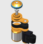
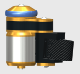
Here is a screen shot of the drive
11.png

Let me know your thoughts.

Thanks.
 
Folken said:
Suddenly, back in 2014... http://newatlas.com/velological-worlds-lightest-e-bike-drive/31976/

No reduction? I wonder how that setup packs lots of copper in that motor for such low KV?
 
cozy35 said:
Folken said:
Suddenly, back in 2014... http://newatlas.com/velological-worlds-lightest-e-bike-drive/31976/

No reduction? I wonder how that setup packs lots of copper in that motor for such low KV?
Easy. The same way as in any friction drive systems with outrunner motors rolling directly on the tyre. Google "commuter booster" for example. Or calculate the required Kv yourself - it's basic math.
 
Yeah, I've seen the Commuter booster using a 190 KV 63MM Motor and some using a 50MM motor, but not too sure there are any off_the_shelf 350 - 450 KV out runner motors in 35 - 42 MM diameter. Hence the reduction drive and using 750 - 1000 KV motor. Besides these smaller motors will lack on the side of required torque, I think.
 
izeman said:
looks cool. would be interesting to see how much torque you can put on the slippery metal surface of the rim, especiall when wet, and how wide the whole system will be, once installed on the bike.

The polyurethane rubber has excellent gripping properties on smooth surfaces. Wet weather riding is another story. I for sure won't be riding in the rain. ;)
 
cozy35 said:
Yeah, I've seen the Commuter booster using a 190 KV 63MM Motor and some using a 50MM motor, but not too sure there are any off_the_shelf 350 - 450 KV out runner motors in 35 - 42 MM diameter. Hence the reduction drive and using 750 - 1000 KV motor. Besides these smaller motors will lack on the side of required torque, I think.
If Kv is too high, just use lower voltages and higher currents. The efficiency will suffer a bit, but a reduction gear is not 100% efficient either.
 
izeman said:
Btw : i just realized that i commented on a post that is totally off topic in the threas. Maybe this discussion should be moved to a new thread.
Cozy35 please make a new thread and ask an admin to move the posts over. :)


I'll oblige, thanks for the pointer.
 
I have been toiling with a friction drive setup to run off the wheel rim sides in symmetrical configuration - i.e. two motors drives on each side of the wheel that is mounted to the seat stays. This setup to also use the inertial start force to engage similar as other swing arm setups in this forum.

After my incorrect posting on another thread I was pointed to a web site where this had in fact been done in 2014 - http://newatlas.com/velological-worlds- ... ive/31976/
Further investigation of this setup shows that they use a cable engage system and a small out runner motor to achieve this. Using a cable engage setup will make operation too complicated and perhaps impossible as a PAS system. As I understand it PAS only engages when a speed of 6 Km/H is reached and has no throttle? Searching for a low KV motor in the 35 - 40 MM diameter case had no results. A 190 KV motor is required for a direct drive to achieve 25 Km/H on a 660 MM diameter wheel @ 3315 RPM on the motor.

My design goal is to use a max of 22.2 Volts and limit that to 12 Amp battery to yield a max of 250 Watts of power and to be able to maintain 25 Km/H on a 2.7% incline, un-assisted.
Someone pointed out that I could lower the system voltage and increase the current, but to get this right for a 750 KV motor I would have to drop the voltage to 3.7 (one cell) and drive it at 68 Amps. I also could not find an out runner motor capable of this high current capability. The idea is to go for a small lightweight and inconspicuous system and after many iterations and calculation I came up with a setup to use a planetary reduction drive setup that delivers the following @ 25 Km/H:

Max 250 Watt, Max 25 Km/H, Max 12 Amp @ 22.2 Volts - Un-assisted, motor KV 663 (So a 750 KV motor will survive the demand) and 12 Amp makes the choice of a variety of ESC's possible. This should make un-assisted inclines of 2.7% possible. On a 0% incline this setup should not require more than 80 Watts to maintain 25 Km/H if my calculations are correct. Given an all up weight of 70 Kg. (Bike and Rider). On a 10% incline the rider would have to assist about 60%.

Now to deviate from the PAS under EU rules, one can go for the off-road mode and disable PAS. The two motors together is capable of a total of 1800 watts. Obviously this will necessitate larger capacity batteries to yield more current and the 750 KV motor can be replaced with a 1000 KV motor of the same physical size to get more speed. At 750 Watts one should get 50 Km/H and 22.2 Volts @ 33.5 Amps. This then also at an incline of 2.7%. On a 0% incline (level surface) it should only require 410 watts @ 50 Km/H. On a 10% Incline @ 25 Km/H, it will require no assistance from rider at 32 Amps.
Getting to the mechanics. I have designed a very compact planetary gear set that is located inside the swing arm. So the motor is in line with the wheel that engages to the wheel rim side. The system output torque demand at 900 Watts (that is the maximum capability of each motor) is 2.34 NM at the gear set output while the motor torque input demand is 0.37 NM. The planet set is designed for a max of 35 ft/Lbs - being 47 NM.

Inertial engagement is by way of the start up spin of the motor against the wheel rim. I have tested with 60A Shore hardness Poly urethane rubber wheels against the smooth surfaces and the grip is super good. There was some concerns raised in the other thread about wet weather riding and I am still to test this. I anticipate that there will be some sort of in line with brake performance in those conditions.

I think I have the mechanics well sorted, but I will need some help with an Arduino based PAS system using off the shelf RC ESC's.
The requirements are:
PAS, Throttle button for off road mode, Wheel sensor (I see some people rely on phase control to limit speed and do not use a wheel sensor input. Current/Phase limit and max 25 Km/H limit.

Here is a picture of the mechanics in 3D. I look forward in any criticism and contribution.

Kind regards
 
cozy35 said:
izeman said:
Btw : i just realized that i commented on a post that is totally off topic in the threas. Maybe this discussion should be moved to a new thread.
Cozy35 please make a new thread and ask an admin to move the posts over. :)


I'll oblige, thanks for the pointer.
 
There is no single perfect drive for all bikes or all riders. However, I'd like to see you put together a prototype and generate some road data. I wish you luck, I think your idea has potential.
 
E-geezer said:
What about carbon rims? :shock:


I haven't tested on carbon rims, but it should also give excellent grip without wear to the carbon. The Poly Rubber will even grip well on glass surfaces. I know this since I developed a Caravan/Trailer Tug to maneuver these into tight spots. U used a heavy duty toothed belt that is 152 MM wide and molded the same Poly Rubber on the outside as tracks. This was tested on water logged smooth floor tiles and did not slip. I suppose one can argue that the weight on the tug overcome slippage. So too I think that the force of the pull-in will also overcome slippage.

I will test his as soon as all my part are machined and installed on my bike.

On a positive note, one can use almost any tire out there.

Here is a pic of the trailer tug.

 
Drunkskunk said:
WHat allowances are you making for when a wheel goes out of true, or is flexing side to side during maneuvering?

Since the motor/drive units are installed at both sides of the wheel on the seat stays, a little out of true will not affect it. The ideal "bite-in" angle is between 48 & 54 degrees, so there is about a 6 degree margin should the wheel go out of true. This much out of true will definitely irritate any rider.

The fact that both drives push against the wheel rim from either side with equal force will overcome any wheel out of true situation.

The drive will totally disengage during power off periods with about a 3MM lift off from the rim.

I think side to side movement during maneuvering is way less than tires out of true or under inflated as I have seen on tire driven friction drives, and they still perform pretty good.
 
spinningmagnets said:
There is no single perfect drive for all bikes or all riders. However, I'd like to see you put together a prototype and generate some road data. I wish you luck, I think your idea has potential.


Thanks.
 
The exploded view of the swing assembly.

Exploded.png
 
It’s got possibilities? Perhaps some sort of “pinching” arrangement which could be mounted to standard brake pivots mounts? Potentially, also serve as a wheel brake system?

It would be nice to have something which can be quickly installed on most any standard bicycle. And this idea wouldn’t wear out tires like mad? Hmm?
 
Ykick said:
It’s got possibilities? Perhaps some sort of “pinching” arrangement which could be mounted to standard brake pivots mounts? Potentially, also serve as a wheel brake system?

It would be nice to have something which can be quickly installed on most any standard bicycle. And this idea wouldn’t wear out tires like mad? Hmm?

The pinching happens by default. When the motors start, the inertial energy swings the driving wheel into the rim about the pivot and engages. The more the torque demand, the more the bite in against rim becomes.

Won't work as a brake. The drives has no friction when no power is applied.
 
I would try to avoid the gear reduction at all costs. There is a very significant loss in the gears and it adds noise and wear issues.

If the rollers were mounted in such a way as to accommodate several mm of runout in the rim it would be helpful. The assembly can float on pivots.
 
Your Rim Friction Drive, Might be the only option for people with newer bikes.

Example :
More and More bikes every month are being designed/sold with the oversize BB30/PF 30 and BB 86/BB92 and other oversize Pressfit Bottom Brackets.
That leaves out being able to mount a Mid-Drive like a BBS02 , Cyclone , Etc. ( The adapters that press fit into a BB30 or BB86 Frame have a reputation of slipping/turning inside the BB Shell of the Frame )
.
Add to that :
At the Same time more bikes each year are redesigned to use " Through Axles "
Yes even the New Road bikes . look at one of the greatest Road Bike Designs to come out in years ... The 2017 Specialized Roubaix !
From the Articles I have read on it , it has just sent the New Benchmark on what most people will be riding in regards to an everyday / long distance / comfortable Road Bike.
The Previous Specialized Roubaix was the most comfortable Road Bike I have Ever Done a Test Ride On, and on the top of the list of bikes to own sometime in the Future when there are enough on the used market.
and many people , Myself probably the first on the list , would love to have one and do an e-motor conversion on it.

Add to that :
That most every bike in the future will have , Both , some kind of oversize/press fit BB, as well as through axles , Just look at all the examples in the 2017 bike line up of most bike Mfg's .
So Neither the current designed Mid-Drives , or , the Current Designed Hub Motors will work for DIY Conversions.

Another Reason Why I Say .... We Need, Must Have , Motors Designed and Made here in the U.S. ! To work with the new , Normal in bike Spec's.
 
You might want to think about Designing / Having Designed for you , Rims that are made just to use with your rim friction drive,
think about the rain and puddles / streams on the trail as well when designing such a rim. and make to be stronger at the contact patch of the drive and rim.
 
ScooterMan101 said:
You might want to think about Designing / Having Designed for you , Rims that are made just to use with your rim friction drive,
think about the rain and puddles / streams on the trail as well when designing such a rim. and make to be stronger at the contact patch of the drive and rim.

Your previous post is right on and I have been mulling this in my mind for quite a while. Puddles won't really wet the rim sides as the water will be dispersed outwards. Riding in rain? I will still do a test with water spray and see if there is slip. Just thinking that old style rim brakes don't really fade all that much when riding in rain so i think the rim friction drive should be OK.

Mid mounted motors suffer from dirt and much build from the front wheel. Up high as on the seat stay is about a safe as can be place.
 
Back
Top