How To, 50A BBSHD Controller Mod

Ebikes4Real

10 mW
Joined
Jun 26, 2016
Messages
25
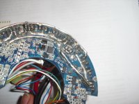
I've started to modify my BBSHD for more current. I've picked out the sealant, to get back to the PCB and I've found a few things:

1. The standard BBSHD controller is fitted with pretty low end mosfets from the factory (P75NF...). Not the same IRFB3077 as come fitted in the 750W BBS02. Hmmm, this might be easier than I expected :wink:
2. It comes standard with a pair of 5mohm shunts, so that means 2.5mohm equivalent resistance. Reducing the equivalent resistance by adding another 5mohm shunt, will mean an actual 45A limit (with 30A programmed), and you can of course, add more shunts, to further reduce the total shunt resistance (reducing the shunt value to 50% of standard, means the controller will deliver 2* the current, therefore double the programmed current limit). I think 45A is plenty, for plus 50% more power (3pcs of 5mohm shunt). All pretty straightforward so far.

I'll update with pictures soon.

Not suggesting this is something, that everyone should try. Definitely do not attempt it, unless you are reasonably skilled with a soldering iron, patient and go into it, knowing that there is a high probability you will wreck your controller. In fact, I suggest you enjoy the standard 30A instead. Pumping 50%, or more power, through this motor, is likely to break something, sooner or later (especially the gear train parts).

A few things to be aware of:
Firstly, it is easy to damage something when picking out the sealant. Secondly, it is rather tricky to remove the mosfets, without damaging the PCB (the way they are fitted from the factory makes it quite difficult to remove the original fets). Thirdly, the rest of the motor isn't going to stand up to a lot more power than the standard 30A (~1500W max), if it is used hard. 12pcs of IRFB3077 seem to be able to reliably provide around 40A max current, so a little more should be possible, but much more and you risk blowing a fet. I'm thinking a 45A limit will do nicely.

I do repeat, it is not a great idea to do this and it will void your warranty. If you are going to do the same, be nice and don't expect your supplier to fix it under warranty, when things start breaking :D
 
Dissolve the water-proofing potting, swap-out the capacitors with higher-efficiency units that are rated to survive 100V, then apply 20S X 4.2V = 84V...then see what pops. If it runs, good...if something fries, post pics and the group will help diagnose how to swap-in a higher voltage component to make it past the next hurdle...
 
Ebikes4Real said:
2. It comes standard with a pair of 5mohm shunts, so that means 2.5mohm equivalent resistance. Reducing the equivalent resistance by adding another 5mohm shunt, will mean an actual 45A limit (with 30A programmed), and you can of course, add more shunts, to further reduce the total shunt resistance (reducing the shunt value to 50% of standard, means the controller will deliver 2* the current, therefore double the programmed current limit). I think 45A is plenty, for plus 50% more power (3pcs of 5mohm shunt). All pretty straightforward so far.

I'm not Dr Maths and have been wrong here before :) , but adding a single 5mOhm shunt will increase current to 41A.
Resistance drops to 1.6666 (vs 2.5 original).
So a 33% increase in current?
 
You can't dissolve the potting, so far as I know, it needs to be picked out. It takes some time, but isn't so bad, once you have some idea where everything is, where the cables go and you have a bit of a technique for it. Of course it would be much easier if you started with an unpotted controller.

The fets are butted up tight onto the pcb, which makes them more difficult to remove, as you can't snip the legs, then remove the leads 1 at a time. There are SMD parts very close to some of the fets, so if you apply too much heat, when removing the fets, these SMD parts can easily come off. Also, it is easy to damage something, while picking out the sealant.

To make the controller work on higher voltages, you'd need to install higher voltage caps and fets, but you'd also need to change the voltage sensing section, to trick the control chip, so it sees a lower than the actual voltage. (just like the R12 mod on the Infineon controllers). The lvc and hvc would need to match that 72V battery. Additionally the low voltage supply section would likely have trouble with a 90V supply voltage, so would likely need some changes. It's all possible to work out, but it's difficult without fairly detailed knowledge of the pcb. I guess, if you got the data sheets for the key components, it could be worked out.

The bbshd already spins very fast, faster than most would pedal, running it on 72V, would make it spin 50% faster. Long and the short of it, going to higher voltage is more involved than upping the current.

Swapping the mediocre standard fets and adding an extra shunt or 2, to increase the standard 30A current limit, is fairly straightforward in principle. Unfortunately, the practicalities of actually making the changes, on a potted controller, makes it tricky to do.

The first controller I worked on got damaged, but the 2nd is doing ok so far. Should have a working 45A controller in a few days with a little luck. Then get it installed on a bike and see how it goes.
 
Gregory said:
I'm not Dr Maths and have been wrong here before :) , but adding a single 5mOhm shunt will increase current to 41A.
Resistance drops to 1.6666 (vs 2.5 original).
So a 33% increase in current?

At 30A with a 2.5mohm shunt, you will have 75mV drop across the shunt.

75mV drop across a 1.666667mohm shunt = 75/1.66666 = 45A

Add 2 additional shunts for a 1.25mohn shunt and now the 75mV drop would be equivalent to 60A. In that case, you need to program to 50% of the required current level, as 60A is a bit OTT.

2.5/1.666667 = 1.5 :)
 
Gregory said:
I somehow feel dumber and smarter at the same time. Thanks for showing your working out!

Well TBH I hadn't run the figures until you questioned it. Was pretty much sure I was right with my assumption, and was rather relieved the figures backed it up :)

Anyways, it's alive and is spinning up the motor. Will get it installed on a bike very soon and see how it performs. Will get some pics up soon, along with a few pointers that should hopefully help to avoid others trashing their controller, if they attempt the same modification.
 
atomek1000 said:
Care to share photos of dissasembly and mosfet replacement? :)

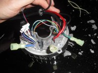
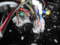
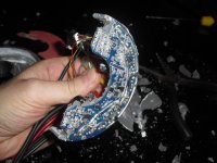
It needs more than just a few pics to explain how to do the procedure, but here some of pictures I took.

It is quite difficult to remove the PCB with heat spreader from the case. After removing the 2 bolts, you need to pick out the sealant, especially where it touches the case. Once much of the sealant was removed, then I found that by pushing a small screwdriver under the PCB, on the same side as the cable entry, then the whole assembly is released a little. Then if you firmly pull on the phase wires, the whole assemble starts to lift out. Once it starts to move, it comes out quite easily, but it is a bitch at first and you need to pull quite hard.

When removing the fets, you need to be careful, not to damage the PCB or let any of the nearby SMD parts fall off. The fets butt up tight to the PCB, so you can either carefully break each fet (with some big cutters), leaving the component legs, which can then easily be extracted 1 at a time. The other option is to heat all 3 legs of the fet and extract each fet in 1 step, but you do risk damaging the PCB when you do it this way (happened to me). Maybe with more practice, the right temp on the soldering and the right tip, this could work well. After wrecking a PCB trying to extract the fets in this way, I went with chopping the fets up and that worked out. The large Cap, needs to be removed as well, in order to remove and fit some of the fets.

I suggest the PCB is confirmed functional, after removing the fets, but before it is built up with the new fets. Ensure there are no shorts between any of the pads on the fets. Do not try to run the controller, just connect it, power on and confirm the display is not giving an ER30. If there are no errors, chances are, you should be able fit the new parts and it will likely work. If you get an error, unlucky.... you must have damaged something, or lost an SMD component. Watch for static too, that can kill this type of device.

When building it back up with the new fets, I fitted about 4 of them (leaving the bolts loose), to the heat spreader, then fitted this to the PCB. Next I dropped in each of the remaining fets into the PCB and then loosely fitted the bolts, securing them to the heat spreader. If you solder the fets to the PCB first, the heat spreader will not line up. The fets need to be fitted to the heat spread (with bolts lose), before you solder them. Once everything is soldered, you can tighten the bolts and fit the large Cap. Before proceeding, check there is no continuity, between the base of each fet and the heat spreader.

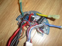
When you fit the new Fets, do another continuity test, to ensure there are no shorts. You can beef up the traces and add another 5mohm shunt (as shown below). With the additional shunt, the controller will provide 45A, when you program it with 30A (1.5*). Fingers crossed, you should now, have a functional 45A BBSHD controller.

Like I said, I am not suggesting everyone goes out and does this, as there is a very big chance, you will wreck a perfectly good controller. If you do get it to work, it will put more strain on the motor (battery too) and you shouldn't then expect this modified motor to be still covered under warranty. These motors are designed for ~1500W max, not ~2200W max, so don't be too surprised is something breaks, or whine about it, if it does :)
 

Attachments

  • CIMG5020.JPG
    CIMG5020.JPG
    99.7 KB · Views: 30,438
  • CIMG5021.JPG
    CIMG5021.JPG
    113 KB · Views: 30,443
  • CIMG5022.JPG
    CIMG5022.JPG
    105.4 KB · Views: 30,445
  • CIMG5025.JPG
    CIMG5025.JPG
    126.7 KB · Views: 30,451
  • CIMG5028.JPG
    CIMG5028.JPG
    112.3 KB · Views: 30,453
  • CIMG5031.JPG
    CIMG5031.JPG
    95.2 KB · Views: 30,445
How much would you charge to perform this modification? :D

Ebikes4Real said:
...When you fit the new Fets, do another continuity test, to ensure there are no shorts. You can beef up the traces and add another 5mohm shunt (as shown below). With the additional shunt, the controller will provide 45A, when you program it with 30A (1.5*). Fingers crossed, you should now, have a functional 45A BBSHD controller.

Like I said, I am not suggesting everyone goes out and does this, as there is a very big chance, you will wreck a perfectly good controller. If you do get it to work, it will put more strain on the motor (battery too) and you shouldn't then expect this modified motor to be still covered under warranty. These motors are designed for ~1500W max, not ~2200W max, so don't be too surprised is something breaks, or whine about it, if it does :)
 
Subd


Sent from my iPhone using Tapatalk
 
Same here. Subscribed !

The thing is, more amps means more torque which is good (assuming we refrain from using that extra torque in steep hills with tough gears, where the already pushed to the edge motor would possibly start overheating or burning) ... But top speed would still be the same since voltage isn't changed...

Upping voltage above 60V on the BBSHD seems like a big challenge. HVC to defy... And I'm not sure if Bafang display would work a 72+ Volts...
There's always the possibility of adding an external controller instead , but I like my Bafang PAS system and display...
 
I tried using the BBSHD with a 61 volt battery. It refused to come on until I dropped it to 60 volts. Then it worked fine. Also, the BBSHDs capacitors are rated 60 volts.
 
If anybody makes this mod again, please try to make a youtube tutorial if possible, so we can all get inpired and learn from it ! :mrgreen:
I'd love to do it myself If I could find a spare BBSHD controller.

Well for the new better IRFB3077 mosfets, i think I know where to look : http://www.digikey.ca/product-search/en?keywords=IRFB3077PBF
Theses ones right ?? (4.95 CAD ; 3.39 USD each; need twelve or so...).

Already have some thermal conducting paste (to put between FETS and aluminium block).
Also need to find proper shunt.

I noticed the PCB have more solder tin for the 30 amps.... Overtinning is a cheap way to add current capabilities.... Might be a good idea to add copper conductors instead....especially given the 45 A capability from this mod.
 
Location of shunts: Look at Ebikes4Reals photos above.
On the third photo down the two shunts are two little rectangles located at about 4 O'clock.
On the sixth photo down you will notice that a third shunt has been soldered on top the other two shunts.

The BBSHD has temperature sensors both in the windings and in the controller. The only reason for Bafang to put them there is to limit power when the temperatures get too high. It only seems prudent to wait and see if the stock lower power mosfets can hold the 45 amps before taking the risky and difficult step of replacing all of them.

You can buy BBSHD controllers from Luna $99
http://lunacycle.com/bafang-bbshd-1000w-replacement-controller/
 
Yeah, I wouldn't replace them unless they blow.

sather said:
...It only seems prudent to wait and see if the stock lower power mosfets can hold the 45 amps before taking the risky and difficult step of replacing all of them...
 
Rumor has it another vendor is having BBSHD controllers built with better MOSFET's. We'll see...
 
sather said:
The BBSHD has temperature sensors both in the windings and in the controller. The only reason for Bafang to put them there is to limit power when the temperatures get too high. It only seems prudent to wait and see if the stock lower power mosfets can hold the 45 amps before taking the risky and difficult step of replacing all of them

Thanks. If we eventually need to unsolder those cheaper OEM mosfets, I think solder wick could help us desolder the fets without overheating the rest of the PCB...

Solder wick is basically copper braid with a bit of flux. So the copper (with it's excellent thermal dissipation capability) helps absorb the excess heat from the soldering iron while the braid absord the liquefied solder by capillarity.
 
Lectric cycles uses IFRB3077 on all BBSHD motors. Apparently always have. Luna now lists their replacement controller as IFRB3077. My replacement controller was the P75NF. I haven't dug into any of my other 3 to see what they are but I suspect P75NF.
But does it really matter? There have been very few problems with controller. All I saw were not MOSFET related.
 
The 3077s will generate way less heat than the 75NF75s. They should survive way more current than the stator could take too. 3077s should handle 60A easily.
 
Back
Top