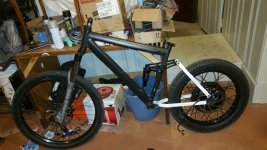
Baron
100 W
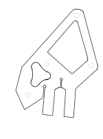
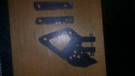
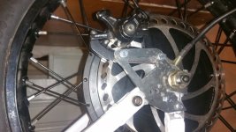
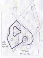
This is my plan for a genesis V2100 torque arm with clamping dropouts and disc brake adapter mounting holes. It would be much easier to get it waterjet cut, but the goal is to use the tools that I have in my garage and some 1/4" thick steel 4"x12" that I have lying around.
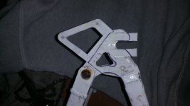
The purple marker is a tracing of the genesis dropout area, and the pencil is the proposed torque arm. Note: these drawings are just mock ups and are not exactly to scale, they're just references to use as I make the torque arm. Don't go putting them in a CAD program and sending them off to get cut unless you want to clean up the lines/make them more accurate.
It's a 14mm axle (10mm flats) but I am leaving room for a 16mm axle too. 1/8" grade 8 clamping bolt because that's probably the biggest I can fit through 1/4" steel. Going to use two nuts and loctite blue to hold the bolt in place. The torque arm will be epoxied to the frame with Loctite metal epoxy and some bolts. But no epoxy will be used around the clamping area to allow the metal to move.
The hardest part will be accurately cutting the dropouts 10mm apart, so I'll attempt that first. probably just going to cut them 9mm apart and file to fit. Next is the holes for the clamping bolt, once I'm satisfied with these, I'll try to fab the rest of the torque arm
View attachment 2
View attachment 1
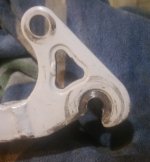
The purple marker is a tracing of the genesis dropout area, and the pencil is the proposed torque arm. Note: these drawings are just mock ups and are not exactly to scale, they're just references to use as I make the torque arm. Don't go putting them in a CAD program and sending them off to get cut unless you want to clean up the lines/make them more accurate.
It's a 14mm axle (10mm flats) but I am leaving room for a 16mm axle too. 1/8" grade 8 clamping bolt because that's probably the biggest I can fit through 1/4" steel. Going to use two nuts
The hardest part will be accurately cutting the dropouts 10mm apart, so I'll attempt that first. probably just going to cut them 9mm apart and file to fit. Next is the holes for the clamping bolt, once I'm satisfied with these, I'll try to fab the rest of the torque arm

View attachment 2
View attachment 1


