Remote On/Off Switch for Phaserunner V2

rberger

10 W
Joined
Mar 9, 2015
Messages
76
Location
Saratoga, CA
I recently got a new Phaserunner V2 that has extra wires in the throttle cable to allow one to set up a remote switch for turning on/off the Controller (and I an presuming also the motor and the Cycle Analyst attached to the controller).

The Phaserunner v2 manual says that "These two wires contain the full battery voltage" which in my case is 52v. I presume that its very low current though since its mainly a signal and the wire gauge is suitable only for signals.

It also says that you should use a "toggle" switch so I presume that it is definitely not a momentary switch and should be the equivalent of an SPST switch.

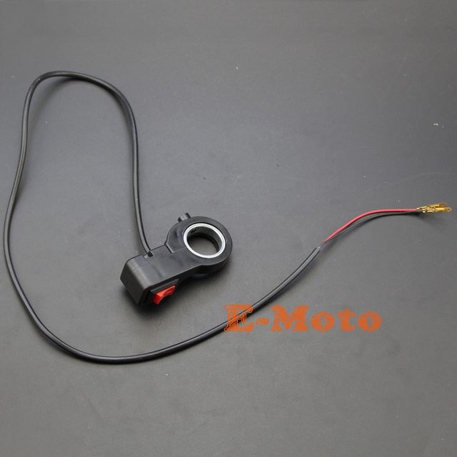
So I am looking for such a switch that I could easily mount somewhere, like maybe on a handlebar / T-Cycle cockpit arm. There seems to be many for motorcycles and such but they are all rated for 12V.

So my first question is: Are all my presumptions correct?

Second could I use a switch that is rated at 12v DC (and probably much more amps than I'm dealing with) for switching the 52vDC here?
Something like: https://www.amazon.com/dp/B0171G7BKC?th=1
 
rberger said:
So my first question is: Are all my presumptions correct?
yes

rberger said:
Second could I use a switch that is rated at 12v DC (and probably much more amps than I'm dealing with) for switching the 52vDC here?
Something like: https://www.amazon.com/dp/B0171G7BKC?th=1
12V switches used to turn on/off battery packs are somewhat of a crapshoot. I've found 12V-rated 15+A switches that work fine with a 14S battery pack whereas other switches rated the same immediately welded shut upon first application.
I know that doesn't answer your question but really, the only way to know for sure is by trying the switch in the application and seeing if it fails.
 
The controller wires you are describing are the same as the 'ignition' wires found in other controllers. These carry battery voltage but only supply a very small current for the processor and a bit of other electronics - something in the neighborhood of 50ma - plus the power for the CA (10ma) and any other accessories you have plugged in to the CA power port. Turning this off kills the processor power which renders the controller inoperable even though the main traction power is still 'on'.

Normally, arcing is not a material problem because of the low current and the switch you describe is certainly more than adequate. That said, the CA power port can supply up to an amp, so there is some possibility of arcing if you load the port and use a switch with really low current capacity.
 
Another option would be to use a simple snap-in rocker switch with a small electronics project box that your mount somewhere on your rig. The tricky part here is that most rocker switches are rated for vac, but I did find a handy conversion matrix for dc applications that is easy to understand.
 
https://cr4.globalspec.com/thread/44970/AC-Switch-in-DC-Circuit
AC rated switches sometimes do not have enough separation to interrupt the arc formed from a DC load. As contacts separate, an arc is formed until the dielectric strength of the air increases to a point that extinguishes t. With AC, the current passes through zero 120 times per second, which aids in extinguishing the arc quickly. With DC, it never passes through zero, so only the distance is used to extinguish it. If the distance is designed around switching of AC only, it may have amost no capacity to switch DC of any appreciable amount of current. As an example, I have used for AC contactors rated for 500A at 600VAC, but they are rated for only 0.4A at 24VDC. There is no guarantee that the switch you are using will function for very long.
 
That is cheap and mounts on the handlebar.
3$ shipped on aliexpress. They have them in many types and groups.

HTB1R1XmNXXXXXXeXFXXq6xXFXXXL.jpg_640x640q90.jpg
 
teklektik said:
The controller wires you are describing are the same as the 'ignition' wires found in other controllers. These carry battery voltage but only supply a very small current for the processor and a bit of other electronics - something in the neighborhood of 50ma - plus the power for the CA (10ma) and any other accessories you have plugged in to the CA power port. Turning this off kills the processor power which renders the controller inoperable even though the main traction power is still 'on'.

So according to the above the Phaserunner V2 remote switch **doesn't** disconnect the battery from the controller where you would need to pre-charge the controller so that you don't have in rush current when turn the remote switch is turned back on?

Is it the same with the Phaserunner V1 switch? "Turning this off kills the processor power which renders the controller inoperable even though the main traction power is still 'on'."
 
This is the same with all controllers. To disconnect the battery, you need a BIG switch, or a small switch + a solenoïd.
 
bobmutch said:
So according to the above the Phaserunner V2 remote switch **doesn't** disconnect the battery from the controller where you would need to pre-charge the controller so that you don't have in rush current when turn the remote switch is turned back on?
Correct.
The V2 remote wiring is essentially the familiar 'ignition' wiring found on other controllers.

bobmutch said:
Is it the same with the Phaserunner V1 switch? "Turning this off kills the processor power which renders the controller inoperable even though the main traction power is still 'on'."
It's the same in function, but not in execution.

The V1 switch is a momentary SPST (ON)-OFF switch that handles very low voltage/current signals to switch the controller processor (and CA) power on/off using an latching circuit in the controller (Push-ON, Push-OFF). Externally, it is not the same electrically as the 'ignition' wire approach and was specifically designed to avoid welding contacts in super cheap external switches. On the other hand, the V2 switch actually switches Vbatt+ to directly cut power to the internal regulator in the same manner as the 'ignition' switch designs (no internal low current latching circuit as in the V1) and so requires a more familiar SPST ON-OFF switch. In either case, the actual battery power to the controller FETs is not switched and the quiescent OFF-state controller current draw is essentially zero.

However, some kind of anti-spark strategy is a good plan if your batteries are removable since there will be a high in-rush when initially connected. I use a precharge resistor and a light gauge 4" wire with dedicated bullet connector for precharge Y-ed off the main Vbatt+ bullet. Plug in the ground, gently plug the precharge for a couple of seconds, then swap the precharge bullet for the main Vbatt+ bullet. Not too fancy but easy to fab and effective when the bulk of the ON/OFF switching is handled with the Phaserunner remote switch gimmick.
 
My solution for this issue was to use a Solid State Remote Switch to switch my main 52 volt main battery power. Handles up to 120 amps and 60 volts. Handy, compact, and comes with it's own cool LED lit push button switch. But you can use any SPST switch for activation. Mounted mine in my front cockpit panel. No need for a pre-charge resistor if your controller's capacitance is below 1500uf.

See my application here...

Then all you would have to do is jumper your controllers "ignition" wire, and use this for total bike power up operation...

See it here... https://lunacycle.com/remote-on-off-solid-state-switch/
 
TommyCat said:
My solution for this issue was to use a Solid State Remote Switch to switch my main 52 volt main battery power. Handles up to 120 amps and 60 volts. Handy, compact, and comes with it's own cool LED lit push button switch. But you can use any SPST switch for activation. Mounted mine in my front cockpit panel.
See it here... https://lunacycle.com/remote-on-off-solid-state-switch/

The REMOTE ON/OFF SOLID STATE SWITCH doesn't have a pre-charge resister circuit (or at least it doesn't state that it does). Besides the glaring lack of a pre-charge resister circuit (unless it's there and they just are trying to trip me up), they should add a fuse into that mix also and provide a XT90-S pigtail.

TommyCat said:
No need for a pre-charge resistor if your controller's capacitance is below 1500uf.

My KT48WS-Zc12 48V 26A Controller had a hash spark. What would be the capacitance of a controller with those specs?
 
Hi Bob,

bobmutch said:
The REMOTE ON/OFF SOLID STATE SWITCH doesn't have a pre-charge resister circuit (or at least it doesn't state that it does). Besides the glaring lack of a pre-charge resister circuit (unless it's there and they just are trying to trip me up), they should add a fuse into that mix also and provide a XT90-S pigtail.

The purpose of a pre-charge resistor is to prevent damage to the connectors or mechanical contacts of a contactor upon connecting the battery to the controller. Caused by a short burst of excessive current from the controllers capacitors charging.

As the solid state relay has no mechanical contacts, and if you stay under the rated capacitance used. The electronics will handle the inrush current.

I would never discourage someone from adding a fuse or circuit breaker to their battery discharge wiring. I rely on my battery's BMS.

The purpose of the SSR is to eliminate the need for XT90s or mechanical contactors. Having it installed in your system, plug your battery into it first, then conveniently power up your bike with a remote switch.

TommyCat said:
No need for a pre-charge resistor if your controller's capacitance is below 1500uf.

Just to be clear... this is if you install the SSR as described above.

bobmutch said:
My KT48WS-Zc12 48V 26A Controller had a hash spark. What would be the capacitance of a controller with those specs?

I have a 25 amp internal controller, with the capacitance total at 1207uf, so I would think yours would be very close. This was found by just looking at the capacitors in the controller and adding them up... Perhaps you would want to contact your manufacturer to be sure.
 
Hi, thanks for the response.

TommyCat said:
The purpose of a pre-charge resistor is to prevent damage to the connectors or mechanical contacts of a contactor upon connecting the battery to the controller.

Um, my understanding was that the purpose of the pre-charge resistor is to pre-charge the controllers caps. It's not the spark that is the problem, that is just the fruit of the problem. The problem is the current in rush in to the controllers caps if they are not pre-charged.

TommyCat said:
The electronics will handle the inrush current.

Ok so perhaps your remote MOSFET switch is turned on slowly and the caps are pre-charged before the full current is "on" and hence there is no in-rush current?

I was reading about MOSFET switches for the last 2 hours and it appears that that can be done.

TommyCat said:
I would never discourage someone from adding a fuse or circuit breaker to their battery discharge wiring. I rely on my battery's BMS.

In my view all battery to controller connections should have a fuse, off/on switch (contactor or others), a pre-charge circuit that is automatic, and anti-spark connectors. Especially when you get up to 72v and over 60A.

TommyCat said:
The purpose of the SSR is to eliminate the need for XT90s or mechanical contactors.

I can see that it replaces a coil activated contactor with the MOSFET switch, if the MOSFET switch circuit is set up correct I am sure it can be setup to open the current flow slowly and get a pre-charge. And as far as the anti-spark connector if you don't have your SSR turned on then the connectors don't need to pre-charge. I still think for $2 or $3 more wholesale the XT90-S 5mm for 90A or the AMASS AM150 7mm for 150A are worth the marking bragging rights to have.

You guys could add all kinds of options into the SSR package. Voltage meter would be a nice one. Fuse would be good.

TommyCat said:
Just to be clear... this is if you install the SSR as described above.

Ya I got the wrong impression with the way you worded it.
 
Wow. Lots to think about here.

rberger said:
Second could I use a switch that is rated at 12v DC (and probably much more amps than I'm dealing with) for switching the 52vDC here?
Something like: https://www.amazon.com/dp/B0171G7BKC?th=1

Regarding the OP's original question, would stepping down the voltage with a DC-DC converter be an option that would enable the safe use of low-voltage switches for on/off-ing the phaserunner? Or is maintaining full battery voltage in that connection required for proper operation of the controller (or other components)?

Regarding connections between battery and controller...

bobmutch said:
In my view all battery to controller connections should have a fuse, off/on switch (contactor or others), a pre-charge circuit that is automatic, and anti-spark connectors. Especially when you get up to 72v and over 60A.

I'm all in favor of redundant safety systems, but my understanding is that XT90s connectors satisfy the need for a precharge circuit (provided you make your connections slowly). Is this not the case? Any tips on making the precharge circuit automatic to reduce the risk of human error?
 
81style said:
Wow. Lots to think about here.

rberger said:
Second could I use a switch that is rated at 12v DC (and probably much more amps than I'm dealing with) for switching the 52vDC here?
Something like: https://www.amazon.com/dp/B0171G7BKC?th=1

Regarding the OP's original question, would stepping down the voltage with a DC-DC converter be an option that would enable the safe use of low-voltage switches for on/off-ing the phaserunner? Or is maintaining full battery voltage in that connection required for proper operation of the controller (or other components)?

... but my understanding is that XT90s connectors satisfy the need for a precharge circuit (provided you make your connections slowly). Is this not the case? Any tips on making the precharge circuit automatic to reduce the risk of human error?
There is no need to reduce voltages to a switch that is basically switching milliamps.

Most switches designed for use in an ICE automobile 'should be tested to survive 60V surges, but whether they are or not is dependent upon the manufacturer.
Above 60V one might as well use a switch rated for higher voltages than one for 12V automotive use, however one must remember that a switch used to turn a controller on/off is switching milliamps, not Amps.
And switching low currents requires much less of everything from a switch. Almost any switch will do. :banana:

As to the second assertion-
no
unless the XT90 has the built-in resistor spark arrestor (then plugged in slowly), it will still spark, no matter what the operating voltages are.

Best practice IMO is using both a controller on/off switch and a battery on/off switch, leaving the controller turned off before reconnecting and switching on the battery.

I remove my batteries before recharging and I have yet to replace connectors or had many switch failures (below 15S battery packs)
 
As a reality check. I have been using that switch (https://www.amazon.com/dp/B0171G7BKC?th=1) for switching the PhaseRunner remote on/off for a year now with no problems...
 
bobmutch said:
In my view all battery to controller connections should have a fuse, off/on switch (contactor or others), a pre-charge circuit that is automatic, and anti-spark connectors. Especially when you get up to 72v and over 60A.


81style said:
I'm all in favor of redundant safety systems, but my understanding is that XT90s connectors satisfy the need for a precharge circuit (provided you make your connections slowly). Is this not the case? Any tips on making the precharge circuit automatic to reduce the risk of human error?

The XT90S will satisfy the need for connecting the battery to the controller if you have your battery switch on. When you turn the battery on with a Contactor you will still need a pre-charger circuit. In most wiring diagrams they will have a pre-charge resister across the terminals of the Contactor. I don't like that because that means the controllers caps are charged all the time and it is also a consistent draw on the battery. So I think there should be a push button so you can change the caps, or a delay relay on the Contactor coil and when you turn your keyswitch on it will turn on a pre-charge circuit and then after a 2 second delay the Contractor coil circuit will close the Contactor.

So the battery switch should be off, the controller turned on, the connectors from battery to controller plugged in, and then the Battery Pre-Charge circuit pressed on for 3 seconds (unless you have setup an automatic pre-charge circuit when the delayed Contactor is turned on) and then the Battery off/on switch turned on.

If you use a MOSFET switch most or almost all MOSFET switches have a cap over the Drain resister so that it slows down the volts on the drain and the MOSFET gets turn own slowly so if you doing a MOSFET switch most of them will do the pre-charge.
 
rberger said:
As a reality check. I have been using that switch (https://www.amazon.com/dp/B0171G7BKC?th=1) for switching the PhaseRunner remote on/off for a year now with no problems...

The Phaserunner switch on V1 or the remote switch on V2 only turns the Phaserunner CPU off and on. It doesn't disconnect the battery from the PR controller. So turning the PR switch off and on doesn't disconnect the Battery from the Controller so there are no issues there with pre-charge or in rush current.
 
Back
Top