Making torque plates for 48v 800w brushless hub motor

Joined
Sep 21, 2017
Messages
26
I want to put a 48v 800w brushless hub motor onto the rear wheel of a small kids motorbike. The hub motor axle does not reach the full width of the swing arm (rear forks) and so I will need to space this out with aluminium or steel blocks fixed to the inside of the swing arm which the axle will locate into. At the same time I need to make a torque plate(one each side) to stop the axle spinning. My question is if I machine these spacing blocks, that will be about 20mm thick each, so that they act as both spacers and torque plates will aluminium be resistant enough (the axle shaped hole itself) to stop the axle spinning taking into consideration the thickness of the blocks or would they be better made of steel.
Aluminium would be much easier to machine .
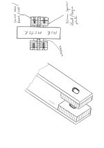
I attach a very amateurish drawing of the kind of thing I mean.
IMG_20171014_0001.jpg
 
Yes, 20mm Alu will do if you buy the harder alloy. You could also buy a fat bike motor that has a longer axle, and make the torque plates outside with 1/4 steel.
 
Jessiedog1234567 said:
Many thanks

Here's an example of aluminum working out well.

https://endless-sphere.com/forums/viewtopic.php?f=3&t=86955&p=1327180#p1327180

Be sure to keep the tolerances tight. I think the clamp on the above example may be partly why his torque arm is working well.
 
Jessiedog1234567 said:
That was my plan GW 100 !
You have nothing preventing the axle from rotating - it's just sitting loosely in the holes. IMO leaving a motor to flop around without fastening it is not going to work for long.

If you want to pursue this strategy, you should consider switching to slots in the plates and build them as clamping plates. This will prevent axle rotation without using nuts. You can bolt them up inside your swingarm, slide in the motor, then clamp the axle in place. You just need to leave one jaw of the clamp unattached so it can move a bit to be tightened down.
 
To me, the drawing in the OP looks like it has axle-shaped holes, which would prevent rotation if they are a tight fit for the axle, and thick enough to cover as much axle flat as possible. (likely, if they have to fill space between dropouts and axle enough that axle cant' be bolted in normally).

Clamping works too (can be even better, as it can be re-tightened even if the original clamp surface becomes damaged and loose for any reason).
 
'Axle shaped holes' will not prevent the axle from rocking and distorting the holes.

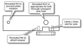
There are many strategies to use, but if I were doing this, I would go in this direction. The slot could be rotated vertically and positioned lower or further aft, etc - lots of options. Here the plates are attached to the frame using a bolt through the existing axle hole with a token M5 around 6" away to prevent rotation. The plates stay bolted up to the bike and changing a tire, etc just requires running out the four keeper bolts (socket head m6). Only needs a couple of small holes for the M5 bolts in the swingarm. No machining really required - hand tools could do the job even if made from steel.

Anyhow - just a thought.

quickieAdapterTPlate.png
 
teklektik said:
'Axle shaped holes' will not prevent the axle from rocking and distorting the holes.

Why not? That is a commonly used method for both commercial and home-built torque arms.

http://www.ebikes.ca/product-info/torque-arms.html

Open end wrenches also use this method (parallel closely placed flat surfaces) for tightening nuts and bolts. If the tolerances are tight and the material is sufficiently substantial, why would the holes distort?
 
wturber said:
Why not? That is a commonly used method for both commercial and home-built torque arms.
Not really. Commercial torque arms rely on axle nuts and the frictional forces they develop to prevent or retard axle rotation. In none of your examples is the axle free to move. See Justin's study on torque arms and effects of nut tightening torque. Drawing parallels with regular torque arms that rely on an entirely different primary mounting strategy is invalid on the face of it.

wturber said:
If the tolerances are tight and the material is sufficiently substantial, why would the holes distort?
Because the Op wants to use aluminum, not steel, and because the axle is steel and the corners of the flat will rock back and forth and impact the aluminum hole on every power application/removal. The design does not have a means to adjust/remove slack that develops. If the plates are fabbed of steel or stainless, then I'm pretty sure the generally crappy steel of the axle will distort from slamming into the flats of the hole since there's nothing to retard rocking motion.

At the end of the day the OP may get away with it, but I can't see a compelling reason to pursue a crap shoot with an entirely new and different mounting strategy when there are other proven designs that are arguably easier to fabricate and require no tight tolerances at all.

But, hey - that's just an opinion... :D
 
teklektik said:
wturber said:
Why not? That is a commonly used method for both commercial and home-built torque arms.
Not really. Commercial torque arms rely on axle nuts and the frictional forces they develop to prevent or retard axle rotation. In none of your examples is the axle free to move. See Justin's study on torque arms and effects of nut tightening torque. Drawing parallels with regular torque arms that rely on an entirely different primary mounting strategy is invalid on the face of it.

Not invalid at all. The issue you raised was the use of axle shaped slots. The examples I linked use axle shaped slots. Axle shaped slots that are fixed into place (not allowed to rotate) are the reason that the axle is not free to rotate. It is fundamental to how many (most?) torque arms work. It is fundamental to how the Grin torque arms I linked to work. Imagine a torque arm with a round hole. It would be pointless.

As for nut compression, are you assuming the OP is not intending to also use nuts to affix the axle? I thought the use of nuts was a given.

wturber said:
If the tolerances are tight and the material is sufficiently substantial, why would the holes distort?
teklektik said:
Because the Op wants to use aluminum, not steel, and because the axle is steel and the corners of the flat will rock back and forth and impact the aluminum hole on every power application/removal. The design does not have a means to adjust/remove slack that develops. If the plates are fabbed of steel or stainless, then I'm pretty sure the generally crappy steel of the axle will distort from slamming into the flats of the hole since there's nothing to retard rocking motion.

At the end of the day the OP may get away with it, but I can't see a compelling reason to pursue a crap shoot with an entirely new and different mounting strategy when there are other proven designs that are arguably easier to fabricate and require no tight tolerances at all.

But, hey - that's just an opinion... :D

But it isn't entirely new. Axle shaped holes aren't novel, they are typical.

You seem to be discounting that each slotted block is 20mm thick. This is aluminum, not silly putty. Heat treated T6 aluminum has a yield strength of nearly 40,000 psi. Heat treated 7075 aluminum is about double that. 4130 steel is about 63,000 psi.
 
There is no doubt that 20mm hard Alu each side will be safe. It is only 800w power, and they could hold 10 kw safely.

Doesn’t mean it is the best way to do the job but it is a safe, acceptable solution.
 
wturber said:
The issue you raised was the use of axle shaped slots. The examples I linked use axle shaped slots. Axle shaped slots that are fixed into place (not allowed to rotate) are the reason that the axle is not free to rotate. It is fundamental to how many (most?) torque arms work. It is fundamental to how the Grin torque arms I linked to work. Imagine a torque arm with a round hole. It would be pointless.
I did not raise the issue of axle shaped holes per se - it is the idea of using them exclusively. The rest of that is drivel - as if the idea of a slot and flatted shaft was somehow baffling in its complexity - seriously?

wturber said:
As for nut compression, are you assuming the OP is not intending to also use nuts to affix the axle? I thought the use of nuts was a given.
If you examined his illustration and posts above you would see that there are no nuts... that is the basis of my concern.

wturber said:
But it isn't entirely new. Axle shaped holes aren't novel, they are typical.
No one said that 'axle-shaped holes' are novel (Seriously?) - again - it's the entire strategy of mounting a motor without actually fastening it to the bike with nuts, clamps, or any other means that is new. Perhaps somewhere someone does this, but it certainly isn't a design mainstay for either commercially available or DIY bikes. This design has the motor just resting in some holes using the axle as pins - no fasteners at all.

I said it above and I'll say it again:

  • teklektik said:
    At the end of the day the OP may get away with it, but I can't see a compelling reason to pursue a crap shoot with an entirely new and different mounting strategy when there are other proven designs that are arguably easier to fabricate and require no tight tolerances at all.

    But, hey - that's just an opinion... :D

In short - even if it can be made to work, there are other simple proven strategies with essentially no unknowns and no risk.

My intent was to give the OP a useful alternative or at least offer some concerns and food for thought - but I certainly appreciate the revelations about how TA's use axle-shaped holes... :D
 
Back
Top