wire connectors a bad idea?

alghul

1 mW
Joined
Nov 17, 2015
Messages
14
Hello,

I have a question regarding the wire connecting the rear wheel motor to my batteries.

Everytime I have a flat on the back wheel, it's a pain to change the tube since the wheel can't be removed completly; the wire is attached to the battery. Last time I brought the bike for a check-up, I asked the guy at the bike shop to change the tube from my back wheel. However, in order to do so, I think he pulled back the wheel too much and the wires near the motor are all stripped.

So, what I want to do is to cut the wire connecting my motor to the battery and build some kind of plug that I could plug and unplug everytime I want to change a flat on my back wheel. I was thinking about using wire connectors. It seems easy enough but I don't think that is very optimal. Also, I would need something water proof.

I would appreciate any ideas.

Thanks
 
You have left out so much info(including your profile), that it's hard to make a specific recommendation, but one thing is for sure. The cable from the motor does NOT go to the battery. It goes to the CONTROLLER, which receives power from the battery.
A commonly used connector is the 9-pin ebike cable connector;
https://lunacycle.com/ebike-kit-extension-cable/
It's good up to about 2000 Watts and is easy to work w/ because it is a sm. diameter and the axle hardware will slip over it.
The ends will have to be soldered on and two sizes of shrink-fit tubing will be used. A very sm. size to slip over each sm. wire in the cable bundle and a larger size to slip over the cable.
Although the connector has 9 wires, you will probably only use 8. The white wire is for a speed sensor, which your motor will likely not have.
 
motomech said:
The cable from the motor does NOT go to the battery. It goes to the CONTROLLER, which receives power from the battery.
Unless its something like the Magic Pie types, where the controller is built into the wheel, in which case it does go directly to the battery (and the throttle/ebrake). ;) Since we dont have any details, as you point out, it could be that type too. But either way, Id go with what youre describing as a fix. :)
 
The A2B bikes also have the battery wires going directly to the motor. And they have connectors so you can remove it for service.

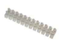
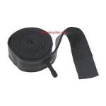
There is no reason you can't put a connector there as long as it's the appropriate type. Anderson Power Pole, XT-90, XT-60 are the more popular types for DIY high power connectors. I have also used a section of Euro style barrier terminal for this kind of thing. They make big ones. None of the above are really waterproof. If the connector is covered with a shroud of some type (piece of old inner tube) or electrical tape, it will be OK.

Terminal Block.jpg
 
The sad truth is that I don't have much info about the bike. I bought it all done and I don't know much about E-Bikes (ex; was not aware the motor was connecting to the controller). I went to 4-5 E-Bike shops and they all told me they didn't want to touch it since nothing on it is standard and they were afraid to ruin it. So my only option now is to do it myself even though I don't know where to start.

I took a couple of pictures of the wire I want to cut.

So, if I go with the extension cable, where exactly do I need to put it? Should it replace the cable I have now? Moreover, you are telling me both ends should be soldered. However, I want to be able to unplug it at will. Maybe I don't understand the purpose correctly so if you could explain to me a bit more, that would be really helpful.

If I go with a little connector (Anderson Power Pole), is the only thing I need to do is cut the wires and put it there in the middle? Do I need one for each of the 8 wires?

Anyway, I know I am a total beginner but that's where I am at. :lol:


It looks like the motor is a 9C or a 9C clone. It's a popular direct drive (no gears) motor that is not very expensive. It's hard to tell from your pic, but the wires where they exit the axle don't look too good. They aren't damaged are they?
To add a connector, the extension, which has a female end on one end and a male on the other, is cut in half. Then the existing cable is cut and one connector is soldered on the controller side and the other connector is soldered on the motor side.
As far as water-proofing the motor is concerned, it's really not possible to fully water-proof it. But there is some things you can do. It appears your motor may have the axle cut-out up-side down. The notch should face down and there should be a "drip loop", that is, some extra length that loops down to prevent water from dripping down the cable into the motor. Adding the connector will give you the opportunity to add some extra length.
 
The wires don't look good indeed but my bike is still working. However, I am not sure if they are going to last much longer if I don't do something about it. They are so close to the axle I can't pull them out a bit to patch them up. Would you suggest opening the motor?

As for the wire extension, I think I understand what you mean but I still have some questions.

Each half of the connectors should be soldered on the existing cable (controller & motor side). Should each of the 8 wires be soldered together one by one (ex. red with red etc.)?

Also, in your previous message, you were saying I would need shrink fit tubing. Should I use the larger size tubing on the whole wire or only where it has been soldered? As for the small size, I get that it should go on the 8 littler wires should they not have it on already?

Thanks for your answers, really appreciate it.
 
I've done a few of these motor cable splices, mainly to use the 9 pin connectors. I've probably been soldering since before you were born, and I still find it a very tedious job. There are two wire sizes in the cable. Three heavier 16G wires for the motor phase wires. Three, five or six signal wires, depending on motor.

The three heavier wires are hard to join. I use the metal tube taken out of a crimp connector and put both bare ends in it and solder. A crimp connector would be better, but is too large. The signal wires are easy. I need small heat shrink for the signals, a little bigger for the pahse wires, and a final thicker piece of heat shrink to cover all. Yes, match the colors of course.

In your case, since the wires are frayed near the end of the motor, you have a harder problem to solve, as there won't be enough wire to solder. The right thing would be to open the motor and reposition the cable. Ugh.

Maybe the best is to cover the ends with liquid rubber. Wrap with tape. Switch to endless inner tubes, where you don't have to remove the wheel. I have used these tubes and they seem to work fine.

index.jpg
 
Doc covered it pretty well.
But I think I would make an all-out effort to try repair the wires at the axle because pulling wires thru the motor is a major PITA.
Since the motor still runs, one can hope that the actual metal wires are not damaged.
Given that you are going to splice in a connector, I would cut the cable about 4 inches from the axle and carefully remove the damaged outer sheathing. Since you will have bought various sizes of shrink-fit, cover any individual that have any damaged coatings w/ the smallest shrink-fit possible. Then slide a long piece if shrink-fit over the bundle and try and get it up and inside the hole. You might even use 2 or 3 pieces. If you mess up and have to cut off any shrink-fit, be careful you don't cut any inner wires. Then I would go to the hardware and buy a length of spring that will slip over the cable, but at the same time, you can stuff one end into the axle opening. Lastly, buy one of these as I think this size fits your motor;
http://www.ebikes.ca/shop/electric-bicycle-parts/u-bracket.html
Splicing and soldering is not rocket science, but takes some practice. You will have enough length in the 9-pin extension that you can cut off some pieces and practice.
Basicly w/ the shrink-fit it works like this;
You will have to expose enough length of the inner wires to be able to slide a piece of shrink-fit long enough, that when you finish the solder joint, it will be long enough to slide down and cover the area where you soldered. The same is true for the outer sheathing, enough length of sheathed(untouched) cable to fit a piece of shrink-fit that went slid down, will cover the un-sheathed area.
Hard to explain, if I could show you, you would get it in a minute.
 
Thanks for the answers. I will try to do that.

A few more questions if you don't mind.

The connector you linked seemed to work out for 1000w motor. However, mine is probably around 2500w. Do you have a recommendation? I looked but didn't find anything.

For the cobra tubes, it seems to be a nice idea. Do you know if they do 2.75-21? The ones I saw all seem to be for smaller tires.

Cheers
 
You are not going to be able to run so much power thru that cheap motor that the connector becomes the weak link.
 
Back
Top