TommyCat said:
That said, the small amount of deflection that you mention doesn't seem worth the trouble and added failure points. Unless your having other issues....?
...thought there was more to it. :wink:
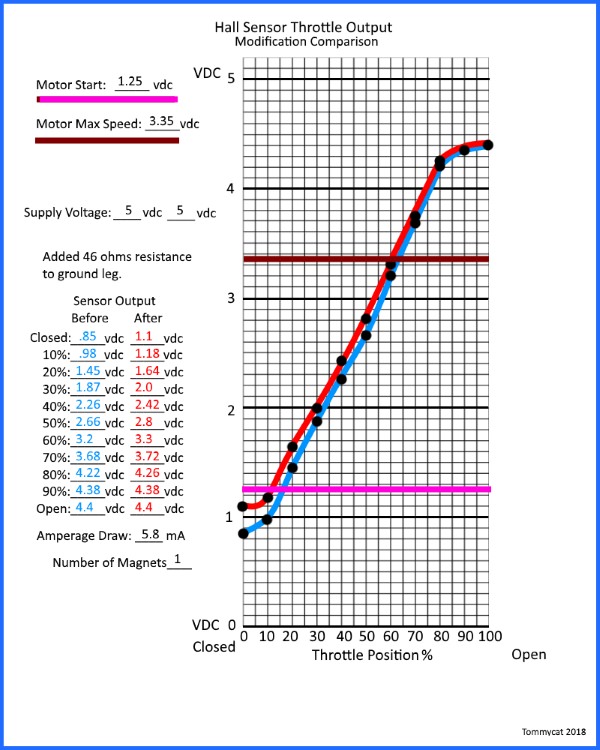
No, just raising the starting voltage does
not change the rest of the total profile like you think. Here is an example of a starting voltage modification by adding 46 ohms resistance to the ground leg. Done on a test rig, no controller attached.
You can see that the ending voltage remains the same. Altho it may reach max motor speed a cats whisker earlier.
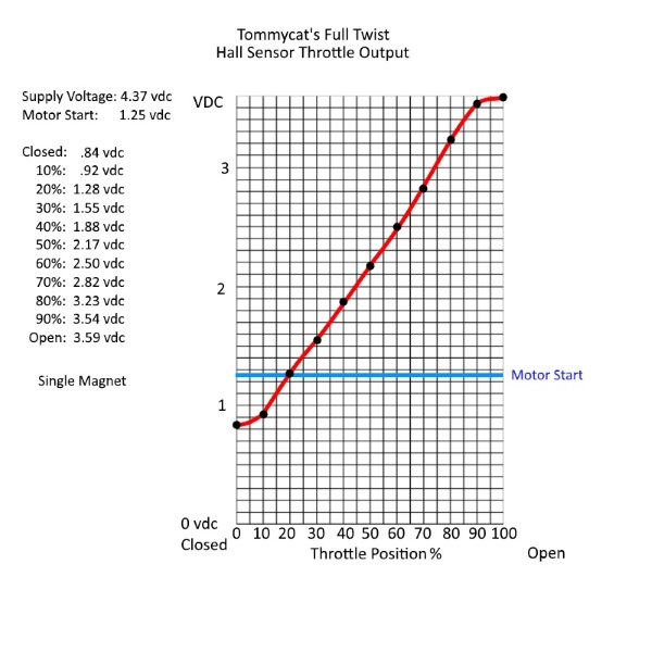
Both my throttles that I have (full twist and thumb) full rotation degrees are ~ 68 degrees. Just to give you some reference. If you desire to shorten that,I don't know an easy electrical way to do it. It would be possible mechanically, but just somewhat easily if you had a 2 magnet throttle.
That said depending on when your motor reaches top end. Perhaps you could block some of the final rotation if it's not needed. In this diagram almost 40% of the ending twist is not even needed.

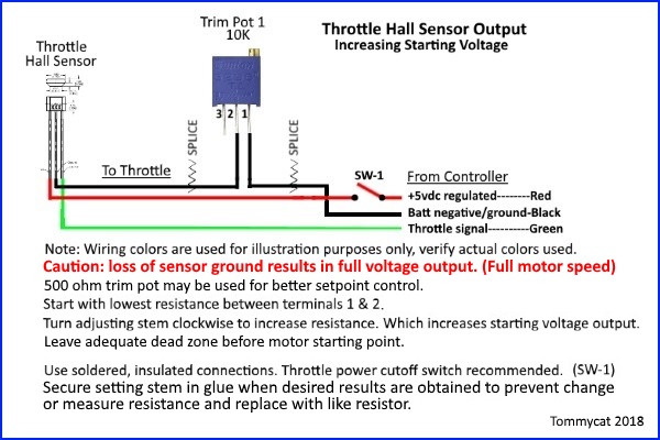
Fechter, good tip on the smaller 500 ohm potentiometer! As you say, more precise control of the resistance input if you have one.