Compound Gearing with two IGH

markz

100 TW
Joined
Jan 9, 2014
Messages
12,179
Location
Canada and the USA
How does one calculate using two normal IGH with a gear mounted on the spoke flange for both IGH?

Crank of 10T going to the regular #1 IGH Gear of 20T
3 Speed IGH internal ratio's are both 75/100/125%
A 30T flange mounted gear going to the normal #2 IGH Gear of 40T with same ratios, and a 50T flange gear.
Going to a 60T cassette on the back 26" wheel.
Both set to 75%

What I do not understand is the crank gear of 10T is going to 1st IGH, with its "normal" operating gear of 20T and the IGH set to 75%, but then there is an added gear mounted on the flange. Different then the common Compound Gearing thats easily solvable.

How does one finish the calculation?


--------
Simpler gearing situations.

With just one IGH
(Out/In)*IGH % Ratio
IGH Gear of 20 / Crank Gear of 10
= 20/10 is 2
multiply
IGH % of 75% = 1.50 on a 26" wheel.
IGH internals 75/100/125%
IGH % of 125% = 20/10=2*1.25(125%) is 2.50

1.50 vs 2.50
IGH at 75% is a 2.50 which is more torque and less speed for same cadence
75% is a 1.50; more speed and less torque for same cadence.

Normal Bicycle
22T Crank and 44T Cassette 44T/22T = 2 for Hills
44T Crank and 10T Cassette 10T/44T = 0.23 for Speed
 
markz said:
What I do not understand is the crank gear of 10T is going to 1st IGH, with its "normal" operating gear of 20T and the IGH set to 75%, but then there is an added gear mounted on the flange. Different then the common Compound Gearing thats easily solvable.

How does one finish the calculation?

Not sure I understand the issue, so maybe my answer isn't what you're after.

YOu'd solve for the first one's ratio exactly as if you were using it in a wheel, cuz it's just a ratio--doesn't matter what it's output is actually tied to.

Then for the second IGH's ratio, whatever the output gear on the first IGH is, you would use as the "crank gear" of the second IGH, as far as calculations go. Otherwise it is calculated exactly the same as the first one.

Then you multiply the two "gear ratios" together to get the total ratio of the system, at any shift point of either IGH (just like you would a front and rear derailer).
 
0.5 (primary chain) x 0.75 (first hub) x 0.75 (secondary chain) x 0.75 (second hub) x 0.833 (final chain) = 0.176.

With both hubs in middle gear, 0.312.

With both hubs in top gear, 0.488.

Why the increasing sprocket sizes as you go back? It's only the ratio that matters; not the absolute size. It's way easier to put a 20t on one side of the hub and a 25t on the other than a 40t on one side and a 50t on the other.

Also, you understand that to stack gearhub reductions like this, you either have to step them progressively leftwards, or you have to join them by way of jackshafts (which allows further gear reduction)? You can't arrange them like the drawing. Input is on the right and output is on the left, always.
 
amberwolf said:

I was totally confused but I think I have it now.
The only part that totally confused me was trying to figure out the Ratio * Gear = Effective Gear just because it is opposite of a Gear on Gear or a Ratio on Ratio and either one is Out/In, or Cassette/Crank.


Its just a math equation that stuck in my brain too long that I wanted to solve.
It came to me while looking at some super steep slopes. In a way its practical I guess, because its not hard to accomplish fabricating something up.

The gear ratio's would be too wide, going too slow, still a fun exercise I guess :roll:
More so boredom :lol:


Next step for this exercise is using a speed/gearing/cadence calculator putting in realistic crank and cassette gears and two Sturmey Archer IGH model AW which has 75%, 100% and 125% and play around with the 4 gears used on them. It becomes 4 shifters in total to be used, if its implemented, big IF!


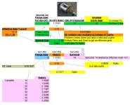
I did a nice spreadsheet to help me out in the visuals.
Start top right. It totally makes sense now.


solution.jpg
 
Please keep in mind that gearhubs have rider weight limits and minimum input gearing ratios that are intended to limit the torque fed into them. When you stack reductions, you multiply the forces into the second hub, which may cause it to fail.
 
Sorry Chalo, I did not see your posts. Had a post open while working on the spreadsheet.
Its not a practical situation, just a "What if"
The gears I chose, were just random to see the final ratio's.

Here is a Spinningmagnets article on IGH and strength, I was going to place this section below but its an interesting read.
Some good info in there, like using a tensioner on the rear IGH for a 2 or 3 crank, dealing with mud, cleaning. https://www.electricbike.com/mid-drive-kit-igh/
mainly concern itself with the strength of the various IGH’s, since we are trying to find appropriate options for mid drive ebikes.


Beyond that, I did a quick IGH search as to different products out there. Tons of speeds now, Alfine700 is up to 11 speeds, some hybrid epicyclic hubs and other hybrids. I know they can get quite expensive. The Brampton BWR is unique, with its 3spd + 2 spd. To do a simple compound gearing, then one IGH with more speeds. In the 1960's SA had a 5 speed, probably could pick one up for a decent price. I personally have two $20 Sturmey-Archer AW IGH (3-spd) in a wheel, that is why I used two in the example.

Played around with a simple formula in the spread sheet, different gears installed. I can't imagine a complete table of final ratio's, cadence and speeds. But I think I will try to do one with a single IGH and 5 speeds to keep it simple.

If this were to be implemented in any fashion, a single IGH with 5 speeds or more, would be nice. A practical situation, if it even is given the forces involved, a rear motor (geared or dd) to a 5+ spd IGH to a triple crank or double. Depending on the final ratio spread and the desires of the riding requirements. Not designed for this imaginary situation.

Doing this exercise give me an interest in the vintage IGH's just because they can be found for cheap sometimes. Unlike the expensive IGH's that are available.

The strength of the vintage IGH's compared to the current IGH's would be interesting to find out. Beginning of post article.
Says 8 speed IGH are strong, use for help on hills which is what got started me on this exercise. Want the best of both worlds, hills and low cadence speed. Will get back to this later, have to hit the road.

Sheldon Brown's statement - The S5s are basically a 3-speed hub with two ranges.


Models
https://sheldonbrown.com/sturmey-archer_5-spd.html#1945

https://bikeshedva.blogspot.com/2017/08/sturmey-archer-four-and-five-speed-hubs.html


Chalo said:
Please keep in mind that gearhubs have rider weight limits and minimum input gearing ratios that are intended to limit the torque fed into them. When you stack reductions, you multiply the forces into the second hub, which may cause it to fail.


Chalo said:
0.5 (primary chain) x 0.75 (first hub) x 0.75 (secondary chain) x 0.75 (second hub) x 0.833 (final chain) = 0.176.

With both hubs in middle gear, 0.312.

With both hubs in top gear, 0.488.

Why the increasing sprocket sizes as you go back? It's only the ratio that matters; not the absolute size. It's way easier to put a 20t on one side of the hub and a 25t on the other than a 40t on one side and a 50t on the other.

Also, you understand that to stack gearhub reductions like this, you either have to step them progressively leftwards, or you have to join them by way of jackshafts (which allows further gear reduction)? You can't arrange them like the drawing. Input is on the right and output is on the left, always.
 
I've tossed around the idea of an IGH as a jackshaft/transmission. Best way to do it IMHO is to keep the bicycle drive train pedal powered then run the IGH output to the left side using a BMX chain. So you pick the motor speed with the IGH and your cadence with the bicycle gears.
I'd keep the IGH spinning fairly fast to limit torque then do as much reduction as possible "downstream" of it.
 
Back
Top