KT motor controllers -- Flexible OpenSource firmware for BMSBattery S/Kunteng KT motor controllers (0.25kW up to 5kW)

you say
Pins on the header from left to right: VCC; SWIM; GND; NRST

I have this ST-Link V2. I guess the "NRST" has to be connected to "SWIM_RST"?

Why don't you power the target with the ST-Link V2? Do you use your Lab power supply (36V)?

Regards
stancecoke
 
I do not connect NRST and works ok for me. But you can try, may work also.

I power with the lab power supply with 30V. The circuit may need much more current than the STLink V2 can handle.

The very first time, you will need to reset/delete the flash memory. I remember that I had to write the default values to the special registers -- I am not on PC so can't help more now.
 
https://opensourceebikefirmware.bitbucket.io/Various--How_to_unlock_proteced_read_memory.html

How to unlock protected read memory

echo "00 00 ff 00 ff 00 ff 00 ff 00 ff 00 ff 00 ff" | xxd -r -p > factory_defaults.bin
stm8flash -c stlinkv2 -p stm8s105?6 -s opt -w factory_defaults.bin

Option bytes with PWM N channels enabled
echo "00 00 ff 20 df 00 ff 00 ff 00 ff 00 ff 00 ff" | xxd -r -p > option_bytes_pwm_n_channels_enabled.bin
stm8flash -c stlinkv2 -p stm8s105?6 -s opt -w option_bytes_pwm_n_channels_enabled.bin
 
OK, for testing your firmware, wich branch do you suggest?
I want to make sure, that the motor turns, just using the throttle...

I made my branch based on the SVM branch.

I just tested the original firmware with the shengyi middrive motor, it worked so far....

regards
stancecoke
 
I created your feature_torque_sensor based on SVM with working motor using throttle.
I just put master branch with the same code.

Try disable first the cruise control, by changing the define about cruise control on main.c.
 
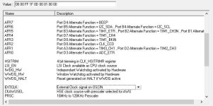
Hm, I was able to disable writeprotect with the OptionByte, but your suggestion for enabling PWM is not accepted.
There's a graphic tool for setting the option bytes, can you tell me the right setting?


casainho said:
I created your feature_torque_sensor based on SVM with working motor using throttle.
this means, with my code the motor is runnig just with throttle, no PAS connected?! Then something went wrong :)

regards
stancecoke
 

Attachments

  • Option Bytes.JPG
    Option Bytes.JPG
    47.5 KB · Views: 3,978
Can't help you more. The bytes need to have this value: 00 00 ff 20 df 00 ff 00 ff 00 ff 00 ff 00 ff

Maybe that graphical software also have an option to be called with the graphical, called by command line -- it is usual as this tools are used on programming when producing a lot of boards, batch programming.
 
Get the STM8S/A Standard peripheral library: http://www.st.com/en/embedded-software/stsw-stm8069.html
and see the examples inside, they are great.

Here online: https://github.com/tonyzouzou/STM8S_StdPeriph_Lib/tree/master/Project/STM8S_StdPeriph_Examples
 
It turns !!! :D

The Option Bytes in the graphical tool are just the relevant ones, like named in the table. I set option byte 2 to 0x20, now it works.
First success!
But the motor turns quite slowly and draws too much current.

regards
stancecoke
 
stancecoke said:
It turns !!! :D

The Option Bytes in the graphical tool are just the relevant ones, like named in the table. I set option byte 2 to 0x20, now it works.
First success!
But the motor turns quite slowly and draws too much current.
GREAT!!

To much current and running slower may mean that angle is not correct... how to adjust it:
- on a serial terminal, send 0 or 1 to increase or decrease ui8_position_correction_value!! You should see motor running faster with lower current. Your target is to have the lowest current value for the same PWM value -- use cruise control to maintain the same PWM duty_cycle value while adjusting the angle.
When you have that value, you should add/decrement to this one: MOTOR_ROTOR_DELTA_PHASE_ANGLE_RIGHT, on main.h.
See that low speed and high speed need different values.... :-( :-(

char getchar1(void)
{
uint8_t c = 0;

if (UART2_GetFlagStatus(UART2_FLAG_RXNE) == RESET)
{
return 255;
}

c = UART2_ReceiveData8();

if (c == '0')
{
ui8_position_correction_value--;
}

if (c == '1')
{
ui8_position_correction_value++;
}

return (c);
}
 
Would be great if you could record a video of the motor running and upload to youtube -- I could later use some images of it in my presentation :)
 
KingQueenWong said:
LSW959-94F Controller Original Firmware Test :D
https://www.youtube.com/watch?v=dCBna4io5-E
Well, the motor seems to do a good noise, like if is running good, however, 3 amps at 33V seems very high!! Compare with my firmware, with also an EUC motor at 64V that takes only about 0.6 amps!!

[youtube]2nDZW4-uVys[/youtube]

I don't know if that controller supports to be configured by this tool:


because I would say the issue is the same that stancecoke is having: wrong rotor angle. And with sensorless FOC, I think the error can come from bad parameters of angle estimator that uses as input the values of resistance and inductance of the coils.

I think you wanted this:
Code:
[youtube]dCBna4io5-E[/youtube]

Result:
[youtube]dCBna4io5-E[/youtube]
 
KingQueenWong said:
LSW959-94F Controller Original Firmware Test :D
https://www.youtube.com/watch?v=dCBna4io5-E
I suggest for you to test LSW-675 as it has LCD/UART connections as also the programming connector and BMSBAttery sells it: https://bmsbattery.com/ebike-kit/543-36v250w-lsw-675-sine-wave-controller-with-lcd-ebike-kit.html

In a few days I should receive my LSW-675 for testing but I prefer to try get a good motor running, with automatic angle adjustment, on the S06S controller - if not, I think LSW-675 is the best bet we can do.
 
I connect the TX pin and RX pin to PC via "USB to Serial module",the lishui controller parameters adjustor application feedback "connection to controller is not detected".
 
KingQueenWong said:
I connect the TX pin and RX pin to PC via "USB to Serial module",the lishui controller parameters adjustor application feedback "connection to controller is not detected".
:-(
Maybe it is kind of locked... maybe just the seller were able to configure and locked it.
I think that app should be used by the seller: let's say BMSBattery want to sell that controller for the Q75 motor, it will configure the motor parameters and after lock the configuration.
 
The seller talk me that my test video is ok,because the controller is FOC controller which is controlled the phase current.High current mean high torque,low throttle mean low current,low current mean low speed.I compare to your EUC firmware,the LSW959-94F firmware can reach larger torque.The seller also talk me that the LSW959-94F can handle up to continous 15A which mean super high torque.
 
KingQueenWong said:
The seller talk me that my test video is ok,because the controller is FOC controller which is controlled the phase current.High current mean high torque,low throttle mean low current,low current mean low speed.I compare to your EUC firmware,the LSW959-94F firmware can reach larger torque.The seller also talk me that the LSW959-94F can handle up to continous 15A which mean super high torque.
I am still not convinced because: "Loosely speaking, torque is a measure of the turning force on an object such as a bolt or a flywheel. For example, pushing or pulling the handle of a wrench connected to a nut or bolt produces a torque (turning force) that loosens or tightens the nut or bolt."
https://en.wikipedia.org/wiki/Torque

Since you are rotating the motor without load, the produced torque should be very small, the only need to beat the motor bearings friction, etc. See this my video, when I implemented max current(torque) control -- verify that current increases a lot when I block the motor with my hand while the motor keep the force/torque on my hand:

[youtube]m6DIowR6jxQ[/youtube]
 
Just found out about this forum after I bought a few FOC controllers on taobao:
https://world.taobao.com/item/544557726531.htm
Going by the taobao sales volume, this is one of the most popular FOC controllers in chinese ebike market.

The bare board item (https://world.taobao.com/item/551416490678.htm) from the same taobao seller seems to use STM32F031C6T6.

Is there anything I can do to help STM32 firmware dev with this FOC controller?
 
zeocio said:
Just found out about this forum after I bought a few FOC controllers on taobao:
https://world.taobao.com/item/544557726531.htm
Going by the taobao sales volume, this is one of the most popular FOC controllers in chinese ebike market.

The bare board item (https://world.taobao.com/item/551416490678.htm) from the same taobao seller seems to use STM32F031C6T6.

Is there anything I can do to help STM32 firmware dev with this FOC controller?
Welcome!!

That one seems the same that KingQueenWong already suggested and seems it is used on the Scrooser.
For now I am betting on the one with STM8 that is cheaper and available on the most stores online for ebikes.
But seems there are much more people with knowledge with STM32...

Can you please how could you help? What experience do you have? Thank you.
 
crossbreak said:
as the main problem seems to be flash memory, what is the STM32F031C6T6 advantage of this 32kb chip over the STM8 that also has 32kb as far as i understand? The F103 with 128kb would be the big shot..no?

GREAT WORK BTW :D
Thanks!!

STM32 is 32bits VS the 8 bits of STM8 plus other differences that make it way faster.

I already did FOC on the STM32F103, as seen on the last video I just post, about current/torque. I would prefer STM32F103 but on the online shops I found the STM8 controller and not easily the STM32 and also there is a big difference in the price of combo controller + LCD. Also the STM8 controller have a good set of features and seems to work well - hard to see the aditional value of other controllers.
 
Regarding the issues with Cute/Q motors:

Translation from this page, for the Lishui LSW-675 using the STM32F103: http://www.groetech.de/index.php?main_page=product_info&products_id=452
Note: The motor speed for sinusoidal controllers is slightly slower than otherwise with normal square wave controllers. The controller does not work properly with high gear ratio (gear ratio over 10) motors like some "cute motors".

Still, there are some reports saying the Q75 motor can't run well with S06P but can run well with LSW-675. Q75 don't have hall sensors and so needs S06P which is different from S06S, as S06P is not sine wave.

Cute/Q85 motors
Reduction ratio: 12.6
Rotor alnico magnets number: 16

328RPM version
• rotor RPM = 328 * 12.6 ~= 4133 RPM
◇ eRPM = 4133 * (16 / 2) = 33056 eRPM

Cute/Q75 motors
reduction ratio: 13.4
rotor alnico magnets number: 16

328RPM version
• rotor RPM = 328 * 13.4 ~= 4400RPM
◇ eRPM = 4400 * (16 / 2) = 35200 eRPM

---------------------------------

http://www.microchip.com/forums/m619210.aspx#619979

I'm building a driver board to work with Field Oriented Control on the dsPIC33FJ12MC202.
Starting from AN1078, I'm a little unclear from reading the App Note and Tuning Guide- what is actual the limit on how fast the motor can be driven?

consider the following timings: -
FOC calculation takes 22uSec. This time also includes the execution time of "estimator" for back emf. The back emf is reflection of the speed of the motor. For a good sinusoidal back emf to be estimated, the estimator should run some 80 samples. Thats an assumption and might vary a little bit.
So, for a good back emf waveform, the sine wave should have 80 samples. So, 80 * 22usec = 1760uSec = 568Hz.
Hence, you can consider that 568Hz (aprox) is the highest electrical speed you can achieve.
If your motor is 4 pole, max mechanical speed = (120 * 568)/4 = 17,000RPM
If your motor is 8 pole, max mechanical speed = (120 * 568)/8 = 8,500RPM

Oznog
I'm looking at different motors too, for different apps. Some would need to go into the range of 20,000 RPM.

For high speed drives, FOC might not be the best option. Try sensorles back emf based drives. Those needs lesser execution and hence can run motor at higher speeds. Try AN1160.
For extremely high speeds, we might want to do away with any executions. That will need external comparator to detect the zero crossing of back emf.

---------------------------------

http://kellycontroller.com/faqs.php

What's BLDC high speed model and ultra high speed model differ from standard model?
32-bit microprocessor, higher PWM frequency.
Standard model: 16.6KHz, 40,000 eRPM.
High speed model: 33KHz, 70,000 eRPM.
Ultra high speed model: 100KHz, 100,000 eRPM.
eRPM=Mechanical RPM*Pole pairs.
It does generate more heat because of higher switching frequency.

When will High speed motor option or Ultra high speed motor option be necessary for the motor?
Please note high speed motor option is only useful for high speed motor.
eRPM=RPM*Pole Pairs.
The standard controller can support 40,000eRPM.
What is the criterion for high speed motor?
When eRPM of the motor is above 40,000, we can call it high speed motor for Kelly controller.
The high speed motor option doesn't mean it will push the motor to get a higher speed.
High speed motor option means that it is capable of catching the hall switching time of high speed motor.
If the motor is 40,000eRPM below, the standard controller can tackle the switching signal from hall sensor.
The motor will run properly.
That is why we don't add high speed motor option to the controller for low speed motor, which is not used to increase RPM.
The speed is the inherent characteristic of the motor. We can not change it.
Just like resistance is the inherent characteristic of the resistor.
Similarly Ultra high speed motor option is only useful for ultra high speed motor(70KeRPM-100KeRPM).
 
casainho said:
- on a serial terminal, send 0 or 1 to increase or decrease ui8_position_correction_value!!

the serial communication should work by default in your svm branch? I tried to write or read something to/from the controller, but there's no reaction.

I expected the controller to send
Code:
printf("%d, %d\n", ui16_speed_inverse, ui8_position_correction_value);
ten times a second at 115200 BAUD to the green wire of the display port?!

edit: I crossed rx/tx, now the communication works.
I get minimum current for correction value of~138. At higher duty cycle this "best" value increases....

I's a little diffcult, as the value returns to 127 each time you stop the motor and it's a little tricky to get the motor running faster than "very slow"

regards
stancecoke
 
stancecoke said:
I get minimum current for correction value of~138. At higher duty cycle this "best" value increases....
And that value need also to change when you increase the current like try braking the motor with your hand.

stancecoke said:
I's a little diffcult, as the value returns to 127 each time you stop the motor and it's a little tricky to get the motor running faster than "very slow"
Try comment the next code:
Code:
    if (motor_state != MOTOR_STATE_RUNNING) // needed to reset ui8_position_correction_value
    {
      ui8_position_correction_value = 0;
    }

To be sure that value is the correct one, you need to measure with an oscilloscope the phase B current signal, at different speeds (there is vias on PCB near the STM8 to measure all the signals):

file.php

The phase current will be a sinusoid if the angle is ok and not a sinusoid otherwise. Do you have an oscilloscope??
The other signal is the hall sensor, which is great as a trigger for the oscilloscope.

ALSO

What is or motor RPM and eRPM? Can you please tell what is the RPM -- max wheel speed x perimeter...
eRPM we need to know RPM and the number of magnets your motor have...

I need to compare your results with my results, because I need to know if the issue if my fast eRPM Q85 motor or the firmware/controller...
 
Back
Top