KT motor controllers -- Flexible OpenSource firmware for BMSBattery S/Kunteng KT motor controllers (0.25kW up to 5kW)

Some bad news...

I have 2 ebikes using LCD5 and just now I figured out that one of them is really different and don't fully work (probably has a different firmware version).

I could understand that when I changed some parameters and suddenly changing the assist level stopped to work. Does anyone knows if is possible to reset all the options on LCD??

I found that the checksum on this LCD was different after I changed that parameters, so, I think in reality we are considering that is the checksum/CRC but it is not or we are doing it incorrectly. Ignoring the checksum, I got the assist level working again but I see that battery bars are always full while If I change for the other LCD, battery bars do work as expected, so, on this LCD, the battery level indication is not working :-(
Note that I configured this LCD to used the latest protocol, just like the other LCD5 that works well.
 
casainho said:
Does anyone knows if is possible to reset all the options on LCD??
Have you tried Parameter C10 for resetting?

casainho said:
Note that I configured this LCD to used the latest protocol, just like the other LCD5 that works well.
What is your setting at Parameter C11?

regards
stancecoke
 
Is the version number of lcd5 on back side different?

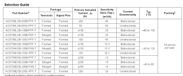
I have another question about phase current, when 6fet has 30A smd sensor, 12fet has 50A, 18fet 100A and there is also 150 and 200A version of that sensor. (You can find pdf easily)

Does it mean it outputs "full" voltage from hall when at the rated current and cant measure more?

Are you using different settings for measuring the phase current on 6fet vs 12fet? If yes, should be added to java tool for each sensor/controller version.. :roll:
 
stancecoke said:
casainho said:
Does anyone knows if is possible to reset all the options on LCD??
Have you tried Parameter C10 for resetting?

casainho said:
Note that I configured this LCD to used the latest protocol, just like the other LCD5 that works well.
What is your setting at Parameter C11?
Thanks!! a total reset with C10 made the battery indication work again. I didn't tested the CRC but I am pretty sure we are doing it wrong... but ignoring CRC, all seems to work (tested with a real ride of 20kms).

For C11, I am using value 0: Meter uses LCD3 new version of communication protocol, it is compatible LCD1 and LCD2..


honya96 said:
Is the version number of lcd5 on back side different?

I have another question about phase current, when 6fet has 30A smd sensor, 12fet has 50A, 18fet 100A and there is also 150 and 200A version of that sensor. (You can find pdf easily)

Does it mean it outputs "full" voltage from hall when at the rated current and cant measure more?

Are you using different settings for measuring the phase current on 6fet vs 12fet? If yes, should be added to java tool for each sensor/controller version.. :roll:
Both say V1.0 on back side but one says after 7B and other 7F.

Looking at datasheet of ACS758LCB-050B used on my S12S, it says:

So I guess it can hold some over current, but for short time - and I would say the output voltage will be limited to the 0 and 5V.
On FOC MicroWorks 30B4 board for electric unicycles, a resistor on PCB is used in parallel with the hall sensor and so less current goes through the hall sensor -- maybe this can be used!!
https://eggelectricunicycle.bitbucket.io/MicroWorks_30B4_board.html

See that on firmware, we use only the sensor output voltage (for "FOC") near 2.5V output (0 amps), so I would say would be no problem if the sensor is working on overcurrent.
The phase current code for "FOC" is just the same code for S06S or S12S :) -- first time I tried, it simple worked :) -- as I told, we are just looking for values near the 2.5V/0 amps, no worry about the amount of current the sensor can read.
 
Stancecoke, about the PI controller:
Code:
void pi_controller (struct_pi_controller_state *pi_controller)
{
  int16_t i16_error;
  int16_t i16_p_term;
  int16_t i16_temp;

  i16_error = pi_controller->ui8_target_value - pi_controller->ui8_current_value; // 255-0 or 0-255 --> [-255 ; 255]
  i16_p_term = (i16_error * pi_controller->ui8_kp_dividend) >> pi_controller->ui8_kp_divisor;

  pi_controller->i16_i_term += (i16_error * pi_controller->ui8_ki_dividend) >> pi_controller->ui8_ki_divisor;
  if (pi_controller->i16_i_term > 255) { pi_controller->i16_i_term = 255; }
//  if (pi_controller->i16_i_term < -254) { pi_controller->i16_i_term = -254; }
  if (pi_controller->i16_i_term < 0) { pi_controller->i16_i_term = 0; }

  i16_temp = i16_p_term + pi_controller->i16_i_term;
  // limit to [0 ; 255] as duty_cycle that will be controlled can't have other values than that ones
  if (i16_temp > 255) { i16_temp = 255; }
  if (i16_temp < 0) { i16_temp = 0; }
  pi_controller->ui8_controller_output_value = (uint8_t) i16_temp;
}
I was having a delay sometimes and so I though there is no point to let I term go to negative values and keep it having only values from 0 up to 255. I tested again it now seems to be working as I expected, without that delays.
 
I am being testing the firmware, on the 2 different ebikes with 24V battery, S06S controllers, Q85 geared motors, LCD5 and torque sensors only. In fact, my soon and girlfriend did ride this ebikes on this weekend for about 20kms. Everything seems to work well :)

Yes, I am really being testing the ebike with our firmware and this bicycle is really strong :) -- that was yesterday and everything went ok:


This was some hours ago, a ride of 20kms:
 
casainho said:
See that on firmware, we use only the sensor output voltage (for "FOC") near 2.5V output (0 amps), so I would say would be no problem if the sensor is working on overcurrent.

Dont understand yet exactly how it works.. but does that mean the model(50,100A..) does not matter really if we dont use it for limiting?

See this chart.
 

Attachments

  • 20180218_184736.png
    20180218_184736.png
    33.6 KB · Views: 1,952
honya96 said:
casainho said:
See that on firmware, we use only the sensor output voltage (for "FOC") near 2.5V output (0 amps), so I would say would be no problem if the sensor is working on overcurrent.

Dont understand yet exactly how it works.. but does that mean the model(50,100A..) does not matter really if we dont use it for limiting?
We are looking for zero crossing of the wave of current, when it changes from a positive to negative value.
Higher current sensor is less sensitive to lower currents, so I would say an S12S should be used for powerful motor that asks more current than one used on S06S.
 
casainho said:
Yes, I am really being testing the ebike with our firmware and this bicycle is really strong :) -- that was yesterday and everything went ok:
Is stuntman you second profession? :) I remember your video with testing regen...

Great, that the PI-controller works satisfying now!
Are you using human power related assistance now, or still just the torque-signal?

regards
stancecoke
 
stancecoke said:
Great, that the PI-controller works satisfying now!
Are you using human power related assistance now, or still just the torque-signal?
Was a little accident and I don't remember last time such happened.

Not using human power, maybe will test later.
The biggest issue is my son not pedalling and resting the feet while the motor keeps running...
I really want power assist at start, without pedalling but also avoid that cheating... Maybe we can think on an algorithm...
 
casainho said:
We are looking for zero crossing of the wave of current, when it changes from a positive to negative value.

Ok, now I understand.

So they use different versions because there is "phase over current" cut/protection on stock fw - I guess.
 
honya96 said:
So they use different versions because there is "phase over current" cut/protection on stock fw - I guess.
I would say they use different versions so the sensor can hold the phase current.
If you are looking to increase the phase current and battery current, I would put the power resistor in parallel with the phase current sensor, as I explained it is used on MicroWorks 30B4 board.
 
casainho said:
honya96 said:
So they use different versions because there is "phase over current" cut/protection on stock fw - I guess.
I would say they use different versions so the sensor can hold the phase current.
If you are looking to increase the phase current and battery current, I would put the power resistor in parallel with the phase current sensor, as I explained it is used on MicroWorks 30B4 board.

Paralel resistor can help only if the phase current is limited, but here its not.
 
honya96 said:
Paralel resistor can help only if the phase current is limited, but here its not.
Maybe it is possible to limit, who knows???
I want to read more about this to learn if is possible.
 
I was able to filter out the torque signal when user is not pedaling and it works well, as expected. I hope that now my son will not be able to cheat :)

The idea is that there is a startup phase where the torque signal is not filtered out. This startup phase has a duration of 5 seconds and after that, the torque signal is filtered out unless the rider pedals (cadence > 0).
The startup phase is restarted every time the ebike wheel speed = 0.

I am now using the external speed sensor for this geared motors, other way this algorithm will not work. Also the user experience is much better with the external sensor installed when using this geared motors.

The code is relatively simple:
Code:
void read_torque_sensor_throttle (void)
{
  static uint8_t ui8_startup_phase;

  read_throttle (); // so we get regular processing of throttle signal

  // calc startup phase
  switch (ui8_rtst_state_machine)
  {
    // ebike is stopped, wait for throttle signal
    case 0:
    ui8_startup_phase = 1;

    if ((!ebike_app_is_throttle_released ()) &&
	(!brake_is_set()))
    {
      ui8_rtst_state_machine = 1;
    }
    break;

    // now count 5 seconds
    case 1:
    if (ui8_rtst_counter++ > 50) // 5 seconds
    {
      ui8_rtst_counter = 0;
      ui8_startup_phase = 0;
      ui8_rtst_state_machine = 2;
    }

    // ebike is not moving, let's return to begin
    if (ui8_wheel_speed == 0)
    {
      ui8_rtst_counter = 0;
      ui8_rtst_state_machine = 0;
    }
    break;

    // wait on this state and reset to start when ebike stops
    case 2:
    if (ui8_wheel_speed == 0)
    {
      ui8_rtst_state_machine = 0;
    }
    break;

    default:
    break;
  }

  // if user doesn't pedal, disable throttle signal
  if ((ui8_startup_phase == 0) && (ui8_pas_cadence_rpm == 0))
  {
    ui8_throttle_value_filtered = 0;
  }
  // use ui8_throttle if cadence is lower than 15 RPM, otherwise, use the processed torque sensor value
  else if (ui8_pas_cadence_rpm <= 15)
  {
    ui8_throttle_value_filtered = ui8_throttle_value;
  }
  else
  {
    ui8_throttle_value_filtered = (uint8_t) (map (
	  ui8_torque_sensor_throttle_processed_value,
	  (uint8_t) ADC_THROTTLE_MIN_VALUE,
	  (uint8_t) ADC_THROTTLE_MAX_VALUE,
	  (uint8_t) THROTTLE_MIN_VALUE,
	  (uint8_t) THROTTLE_MAX_VALUE));
  }
}
 
honya96 said:
Or hardware modification, which I will like the best, but is really hard.
A)
Adding 1 more hall current sensor to the last free AIN pin. (Sensor can be on wire, so not that hard do do for me) adding 2 more will be best but we dont have enough free pins?

Or

B) Using mosfets as shunts (is done on some controllers) but then we need amplifier?

Then even true FOC will be possible.. but I saw somewhere Casainho whote stm8 doesnt have enough processing power.
For doing FOC, we really need an STM32, no point to try do with STM8.
Ideally, we would find a "cheap" motor controller that original firmware does FOC, like this ones: http://en.ertcz.com | https://ertcz.en.alibaba.com/
 
casainho said:
honya96 said:
Yes, actually not even 0.5 second with really fast motor, because 40A from battery can be 200A to motor. (=at mofets)
Didn't know about that!! Now I recall Stancecoke and others telling that "motor current" on firmware is instead battery current but I always thought they were equal.
I need to read more about it and I found this one shunt used on this controllers, is referred as "DC-Link Current Sensor".
I found an application note from ST talking about measuring phase current with "satisfactory results", that I think is to be done with the same hardware we have in our hands: http://www.st.com/resource/en/application_note/cd00075973.pdf

Can you guys gives give a look and give some feedback?

NOTE: I am being enjoying my Q85 motor, torque sensor, Ebike, on nice sunny days :)
 
casainho said:
For doing FOC, we really need an STM32, no point to try do with STM8.
Ideally, we would find a "cheap" motor controller that original firmware does FOC, like this ones: http://en.ertcz.com | https://ertcz.en.alibaba.com/

Just theoretical question. Is stm32 exactly pin compatible and really easy to run the same fw?

Still easiest to do the current ramp first as I suggested, will be good enough for most people. If set well.

But if anyone else interested, I can add second phase current sensor to s06s s12s and 18fet and do tutorial for each with basic tools so anyone can do. Then it can be optional in java app, and enables exact phase current setting/limiting from total zero speed (which I guess mathematical model cant do that well)

Maybe not worth adding it for most s06s since its mainly for gear motor and low power.

I know you guys dont see it as a huge problem right now,

but the better phase current limiting, the more high power bike users not having to spend in average 300-900$ on controller, which fails right after warranty and repair costs like 2 new kuntengs
 
honya96 said:
casainho said:
For doing FOC, we really need an STM32, no point to try do with STM8.
Ideally, we would find a "cheap" motor controller that original firmware does FOC, like this ones: http://en.ertcz.com | https://ertcz.en.alibaba.com/

Just theoretical question. Is stm32 exactly pin compatible and really easy to run the same fw?

Still easiest to do the current ramp first as I suggested, will be good enough for most people. If set well.

But if anyone else interested, I can add second phase current sensor to s06s s12s and 18fet and do tutorial for each with basic tools so anyone can do. Then it can be optional in java app, and enables exact phase current setting/limiting from total zero speed (which I guess mathematical model cant do that well)

Maybe not worth adding it for most s06s since its mainly for gear motor and low power.

I know you guys dont see it as a huge problem right now,

but the better phase current limiting, the more high power bike users not having to spend in average 300-900$ on controller, which fails right after warranty and repair costs like 2 new kuntengs
Let's see if the way indicated by ST for measuring phase current with our hardware gives the "satisfactory results".

Next step in upgrade is a controller with STM32 and hardware that can do FOC like this: http://en.ertcz.com | https://ertcz.en.alibaba.com/
The thing is that firmware is complex and take time, we need to find someone that will have the controller on the market for the next 5 or 10 years.
 
casainho said:
Let's see if the way indicated by ST for measuring phase current with our hardware gives the "satisfactory results".

Next step in upgrade is a controller with STM32 and hardware that can do FOC like this: http://en.ertcz.com | https://ertcz.en.alibaba.com/
The thing is that firmware is complex and take time, we need to find someone that will have the controller on the market for the next 5 or 10 years.
Just use open source hardware, PCB + assembly services are so cheap small production runs are easy these days. I think there's even a few places that will handle ongoing production and online sales for open hardware if you can show people are willing to buy them. One thing I have found when using the VESC though is the STM32 can be a little lacking for motor control, there's quite a few 32bit MCUs from Ti, infineon and analogue devices that are much more focused on motor control, small details hidden away in the datasheets can make quite a big difference, PMW resolution, ADC conversion time etc. vary more than you would expect. While certain peripherals can make hardware designs quite a bit cheaper on higher power controllers.
 
I think I got the motor phase current from the shunt, by following the ST application note. I also did some tests and did a log, where I did validate the results with the mathematical model.

My notes: https://opensourceebikefirmware.bitbucket.io/development/heets_and_application_notes--Endless-sphere.com_forum_messages--2018.02.20_-_Reading_motor_phase_current_from_the_DC_link_current_(shunt).html

---

Following the application note: Linked file: AN2267 - Implementation of current regulator for BLDC motor control with ST7FMC.pdf
it should be possible to read motor phase current with “satisfactory results” from DC link current (shunt current).

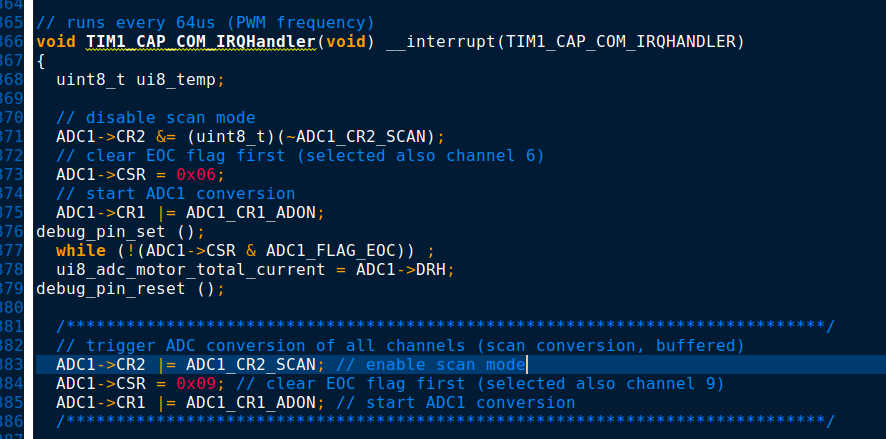
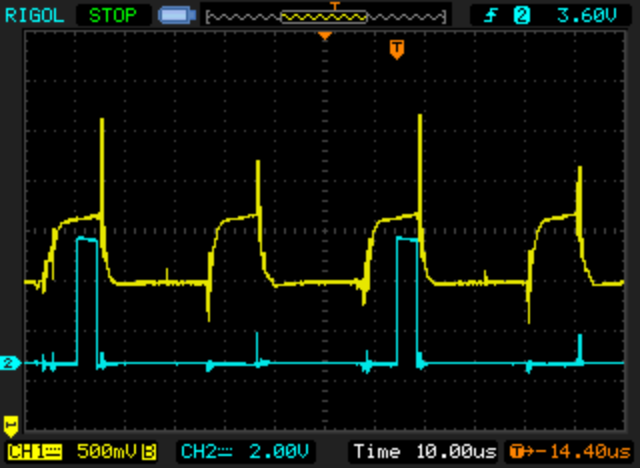
The PWM interrupt code was changed so the interrupt always happen at the middle of current pulse. The ADC channel 6 reads the pulse value at start of interrupt and after all the other ADC channels are read.
Note the line debug_pin_set (); that is when ADC channel 6 read happens and will enable a digital pin so we can see on the oscilloscope.
118-1.png


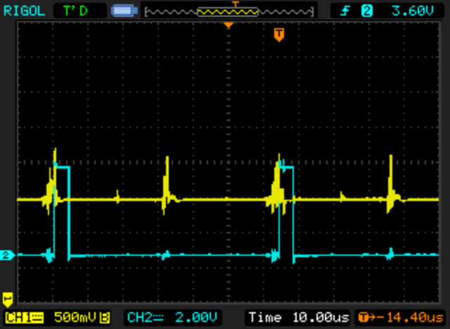
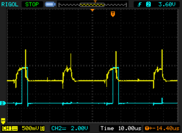
And on oscilloscope, blue line is the digital pin signal used for debug and as we can see, the pulse (yellow line) is read by the ADC right on the middle.
Yellow line is shunt voltage (after amplification).
The next pictures show different current values and that signal is always read at middle.
Note that the firmware only reads 1 pulse every PWM cycle while there are 2 pulses every PWM cycle.
118-2.png


118-3.png


118-4.png


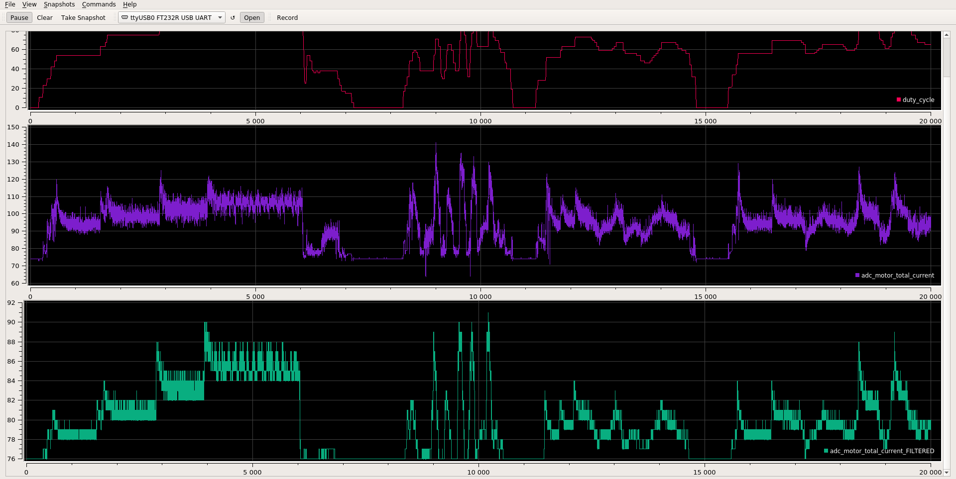
And log from real values:
118-5.png


Validation
Example of point on the graph:
- duty_cycle: 85 (33%)
- battery current (green line): 82
- motor phase current (purple line): 100
- lab power supply was measuring 2.5 amps

1. Battery current was 2.5 amps. The green line had a value of 83, which is a delta of 8 (83 - 75, where 75 is the ADC value for 0 amps), so every ADC step is 2.5/8 = 0.31 amps.
2. The motor phase current had a delta of 25 (100 - 75), which represents a value of 25*0.31= 7.75 amps.
3. The mathematical model says that: battery current = duty_cycle * motor phase current. As the duty_cycle was 33%, so the motor phase current should be (battery current / 0.33) = 2.5/0.33 = 7.6 amps <--- the measured values seems to be inline with the mathematical model.
 
honya96 said:
Is the version number of lcd5 on back side different?

I have another question about phase current, when 6fet has 30A smd sensor, 12fet has 50A, 18fet 100A and there is also 150 and 200A version of that sensor. (You can find pdf easily)

Does it mean it outputs "full" voltage from hall when at the rated current and cant measure more?

Are you using different settings for measuring the phase current on 6fet vs 12fet? If yes, should be added to java tool for each sensor/controller version.. :roll:

The allegro ACS sensors are a little complex, they clarified it on the latest datasheets for newer models. For a sensor with a rating of +/- 50A it has a sensitivity of 26.4mV/A, with the 3.3v model the output at 0 current is 1.65V, 26.4mV x 50 + 1.65V results in 2.97V output, which is less than the max 3.3, this means the absolute maximum current the 50A model can measure is approx +/- 62A, however the data sheet says this is outside the range where the sensor is accurate at max output current is likely anywhere between 56A and 72A, anything beyond that is impossible to measure, the sensor can only output a maximum of whatever the supplied VCC is.

Basically you have to configure any software based on the mV/A value but keep in mind the sensor is only accurate within its listed current rating.
 
lizardmech said:
Just use open source hardware, PCB + assembly services are so cheap small production runs are easy these days.

@casainho - if you decide to try this way, I can do like 2 testing units, to find if there is a need for any pcb improvment, and then batch of like 10pcs at component price for fw developers.

I guess we can easily make it work with kt-lcd series, or any other, right?
 
lizardmech said:
Basically you have to configure any software based on the mV/A value but keep in mind the sensor is only accurate within its listed current rating.

@casainho - So if we you use the value from sensor, we need parallel resistor as you said.
 
casainho said:
The mathematical model says that: battery current = duty_cycle * motor phase current. As the duty_cycle was 33%, so the motor phase current should be (battery current / 0.33) = 2.5/0.33 = 7.6 amps <--- the measured values seems to be inline with the mathematical model.

Dont understand much of the post and stm7 pdf but if this part is true, phase hall can be still just for zero crossing and phase current calculated and set really easy. (?) :)
 
Back
Top