magnets held without glue?

Joined
Apr 25, 2014
Messages
2,798
Location
Sausalito
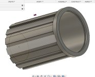
what motors do it like this without glue?Capture.JPG

ive seen it with aluminum but seems mechanically sketchy and was thinking of trying it with a mild steel ring. if in steel would the ring mess with the magnetic circuit or better direct it? im guessing it would help and maybe could shape the steel ring some best way probably, probably just closer to the stator and get some axial action. :bigthumb:

magnets seem so hard Id like to try pressing them into a slightly too tight ring, or maybe that's how its typically done.
 
Any iron In the motor needs to be laminated a big block of iron will get hot,
Problem being some magnets will attract to their position while others will oppose and be flung out so we have to secure them in place be it with glues or tounge and groove etc.
 
Ianhill said:
Any iron In the motor needs to be laminated a big block of iron will get hot,
Problem being some magnets will attract to their position while others will oppose and be flung out so we have to secure them in place be it with glues or tounge and groove etc.
But is it IN the motor where it would be experiencing switching fields I think not. It's the back iron which is used to direct the field but not within a switching field. Maybe if going for super efficiency the losses there would be a thought I think.
 
I would recommend that you do a quick search of Interior Permanent Magnet / IPM (compared to the common surface mounted magnets) Those designs are useful, especially for a motor with high RPMs...
 
Since IPM motors puts the magnets in the steel it’s somewhat similar to your question but then the steel is laminated.

If you’re at a reasonable distance from the coil fields it’ll work with a metal keeper ring without creating excessive losses but i think having a steel keeper ring would short out some of the flux that’s supposed to be in the airgap.

7075 alu is stronger than mild steel, no reason to doubt it for a keeper ring.
 
larsb said:
Since IPM motors puts the magnets in the steel it’s somewhat similar to your question but then the steel is laminated.

If you’re at a reasonable distance from the coil fields it’ll work with a metal keeper ring without creating excessive losses but i think having a steel keeper ring would short out some of the flux that’s supposed to be in the airgap.

7075 alu is stronger than mild steel, no reason to doubt it for a keeper ring.


For a typical motor you say the aluminum is fine but this would be in a skateboard hub motor with a lot of stress on the roto from the road. Maybe the slightest bending of the rotor transferred through the magnets to the ring is minuscule but maybe would fatigue. Maybe good modeling could be done to realize the stress that would be on the ring. And then glue doesn't last forever either.


When u say short the flux I'm visualizing the flux line going n to s, and the line being very short completing the circuit just wrapping the magnet and wasted at the end of the magnet, so maybe if used a 54mm long magnet and 2mm each side where the magnet would be magnetically lost to the motor with a 48 or 50mm stator. I imagine the magnet being extended a bit beyond the stator is a boon but if I clamped down the magnet beyond there..it would be possibly unrelated to the magnetic circuit of the motor. ?
 
Alu will be fine but a solid piece of mild steel not so much, I see u want exceptional high rpm rotor the way to this would be make the magnets weight less by having high strength and good balance.

I see the magnets have to be longer than they need to be so there more mass and cost there has to be a way of locking them from the inactive face to keep the magnet small possible and mass down do you plan on going into the 20k+ rpm range then ?
 
Ianhill said:
Alu will be fine but a solid piece of mild steel not so much, I see u want exceptional high rpm rotor the way to this would be make the magnets weight less by having high strength and good balance.

I see the magnets have to be longer than they need to be so there more mass and cost there has to be a way of locking them from the inactive face to keep the magnet small possible and mass down do you plan on going into the 20k+ rpm range then ?
the math is melting my brain but I think relatively slow turning motor for a skateboard hub motor. 45kph, 84mm wheel diameter.

thanks for your advice on the ring. how do you both feel so confident aluminum is fine and what of cheap aluminum? are there any examples of it being done you can show? what do you think of a glue-less method like this compared to good glue?


like 2cm of rubber between this and the road is rough.

its not imbedded magnets but 14 teeth on the outside being thicker make a big difference lined up between the magnets. an imbedded magnet design would be slick but does it need laminates? I thought it was only the stator side that really experienced hysteresis maybe eddy currents in the magnets but I didn't think there was much iron loss on the rotor side. No?
have to crank up motor solve again. where is a good guide for connecting that stuff to most common parlance and practical application? ill have to search youtube again but I wish someone who really knows that program would do a video starting with "ok here's what you want to know..."
 

Attachments

  • Capture.JPG
    Capture.JPG
    45.7 KB · Views: 1,049
Magnets should be roughly (stator width + 2x magnet thickness) wide to catch most of the available flux.

You’d need some added rotor width to fit a keeper ring and the sideplates, ring would give extra stiffness to the rotor as a bonus
 
Makes sense if u could fit the long magnet, but then if u can fit the longer magnet why not put a longer stator as well.

On the hunt for design help in earnest.
 
WIN_20190927_16_09_25_Pro.jpgWIN_20190927_16_09_35_Pro.jpglook how little room there is here. ive done them closer. how much of a loss from eddy currents or hysteresis could be happening?
I somehow concluded years ago the losses even if the windings were even pressed against the steel wall would be negligible and I typically am maybe 1mm or 2 max away. im gunna go play with motorsolve and emetor
 
https://spectrum.ieee.org/transportation/alternative-transportation/this-insideout-motor-for-evs-is-power-dense-and-finally-practical

Here's a tip if you want extremely high power dense motors u need to move from a traditional layout to axial, 12kw per kilogram has been achieved with state of the art designs there's no reason why it can't be emulated, with careful analysis of the basics theres ways of drastically improving the power handling without actual being a master but rather following the hurd don't get to bogged down in the math, get the basics sorted through experiment u can't make a ommelte without cracking eggs.

If your making a hub motor then think about making the centre core/armature a pancake and the side cover would contain the magnets and be bolted on same as a usual hub the axle would be solidly bolted firm while the casing rotates so the windings will need attention ferrofluid can only do so much a small dual core pipe could deliver and remove a coolant down the axle just like the phase wires opposing.

This would be a big step up in terms of design compared to most and theres no extra cost in material its just resesrch and development and it's like the hurd doesn't want to move on the hub motor front there's been a stall a lazyness acceptance of heavy DD hub motors from qs and mxus making more power by just increasing the size of old designs with little change when it doesn't have to be this way and the power output could be drastically improved and remove the dreaded heat problem, the rest of the market would have to listen up and follow suit and advance to simular designs.

The commercial ebike motor market from bosch and alike is moving alot faster because of alot more cash interest than the diy front so it needs a kick up its arse and use their brains to blow people away and draw them to the dark side of diy.
 
Back
Top