Does adding more cap to the DC bus on a controller help? Look in here for the answer.

zombiess

10 MW
Joined
Jan 31, 2011
Messages
3,048
Location
Oklahoma City
This was inspired by a resurrection of Doctorbass's old thread about adding ceramic caps.

Adding caps to the DC rails can provide some minor improvement, but it often will not solve major turn off overshoot. Here are some simulations with relevant parasitic RLC parts modeled.

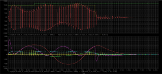
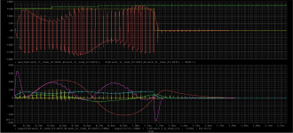
This layout has ~45nH of measured parasitic inductance (4nH on the DC Bus, if made lower the turn off overshoot will be lower). Testing is 1kHz sin, 30kHz bipolar PWM, 50V DC bus 2 parallel devices, full H bridge, 500ns dead time. 100uH/100mOhm load coil.

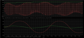
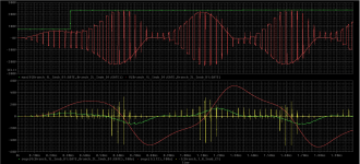
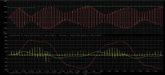
On the top graph, you can see the green line shows the maximum voltage reached, the red is what the input to the load coil looks like. The lower graphs show a 100us moving average of the voltage and current waveform. Green=V, Red=Amps

No snubbers at all
1kHzSIN-30kHzPWM-NORCDsnubber.PNG

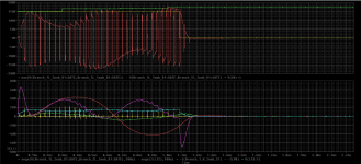
A overspec'd (designed for 400A, 150V bus) RCD snubber.
1kHzSIN-30kHzPWM-RCDsnubber.PNG

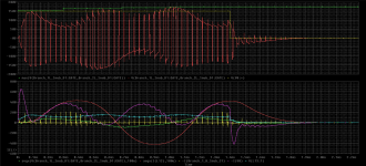
Adding 1uF cap to each half bridge
1kHzSIN-30kHzPWM-2x1uFbusCaps.PNG

Adding 10uF cap to each half bridge
1kHzSIN-30kHzPWM-2x10uFbusCaps.PNG

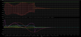
Adding 100uF cap to each half bridge (distributed DC link at this point)
1kHzSIN-30kHzPWM-2x100uFbusCaps.PNG

As you can see, adding more caps to the DC link can provide a small improvement, but nothing will beat a proper snubber design on a low inductance layout.
 
So is it possible to make your own snubbers or they have to be embedded on the pcb itself?

Ive heard a few things about them but not much on how to make one, if the speed controller pcb design does not have it.

Seems like major safety improvement, which has not been widely enough executed, at least on some older design Vesc's.

Sent from my ALE-L21 using Tapatalk


Okami said:
So is it possible to make your own snubners or they have to be embedded on the pcb itself?

Ive heard a few things about them but not much on how to make one, if the speed controller pcb design does not have it.

Seems like major safety improvement, which has not been widely enough been executed

Sent from my ALE-L21 using Tapatalk

It could be possible to add a snubber onto an existing controller, but at that point it's a band-aid on a sub optimal design, but as they say, if it works...

You can search for RC and RCD snubber calculators, but be ready to start digging deep, you really need to understand what is going on to choose the correct components.

My overkill snubber in the above was designed to handle 400A transients (time limited by thermal) with 150V DC bus on a 25uH load. To do so requires schottky diodes on the snubber that can handle close to 400A peaks and low ESR caps which can take 200A peaks. It's part of a new 150V (200V MOSFETs, 600V IGBTs possible) 3phase powerstage/gatedrive setup I'm planning to release to the maker community in the near future as a complete unit, just add your own motor controller (Lebowski, VESC,etc. I'm working on a VESC control board and borrowing concepts from Shaman and Axiom's design to find a middle ground) or whatever your goal is. Keep in mind that I already have experience in power electronics and this snubber design took me almost a month of learning and playing around in simulation.
 

Attachments

  • 150V-400A-1kHzSIN-30kHzPWM-RCDsnubber.PNG
    150V-400A-1kHzSIN-30kHzPWM-RCDsnubber.PNG
    91.9 KB · Views: 1,107
Does a large inductance between battery and DC link change the voltage situation?
For example during normal operation and also when the BMS disconnects the battery at peak current.
 
Thanks for clarifying.

Yes, im pretty much noob about custom made brushless motor speed ontrollers but Shaman was the guy which made it more understandable for the common guy.

Kudos to him for that.

So seems like if developer is keen enough and spends his time to calculate components with the right specs, it can be rewarding for the end user.

Especially for end users who might face high enough voltage spikes and thus might save their speed controller from burning up, if main battery voltage was already too close to power component voltage limits.

Sent from my ALE-L21 using Tapatalk


marcos said:
Does a large inductance between battery and DC link change the voltage situation?
For example during normal operation and also when the BMS disconnects the battery at peak current.

Yes, it does change things.

As simulated above, the battery to DC link was 150nH. I just ran it at 15uH and 150uH battery lead for fun, but I haven't simulated a disconnect yet. I added the peak current into the snubber cap in yellow.

These graphs demonstrate why it's important to keep your battery leads short... and not connect the battery to the controller through a 150uH inductor cause you want to be a weirdo.
 

Attachments

  • 150V-400A-1kHzSIN-30kHzPWM-RCDsnubber-150uHBatt.PNG
    150V-400A-1kHzSIN-30kHzPWM-RCDsnubber-150uHBatt.PNG
    88.5 KB · Views: 1,102
  • 150V-400A-1kHzSIN-30kHzPWM-RCDsnubber-15uHBatt.PNG
    150V-400A-1kHzSIN-30kHzPWM-RCDsnubber-15uHBatt.PNG
    88.7 KB · Views: 1,102
I'm going to take a stab at sorting out what is needed on a sudden disconnect with back of the napkin calcs.

Energy stored in an inductor is 0.5 LI^2, so 150nH has:
0.5 * 150nH*400A^2 = 12mJ

Capacitance overhead required to absorb 12mJ = 0.6uF (calculated at 200V because of device avalanche and assuming low enough cap ESR). My snubber setup is oversized with 4.7uF 450V caps, so even if the switch device needed to absorb this transient on disconnect, I'm pretty sure it would be ok.

I got to this by following:

Charge: Q = CV where C is the capacitance in Farads, V is the voltage across the capacitor in Volts and Q is the charge measured in coulombs (C).

Energy stored: W = ½ QV = ½ CV2 where W is the energy measured in Joules.

Now if you did have 150uH of battery lead inductance, you would need to have 600uF of capacitance to handle it and that doesn't exist on my design, but this is la la land IMO, unless you like really long battery leads not twisted together and coiled tightly; I'm looking at you noob end users with 12ft long jumper cables... not that I've ever done the same :mrgreen:

Of course maybe I'm looking at this from an incorrect perspective as I haven't thought about it in detail, just since you mentioned the disconnect. Now I need to ponder it some more. Someone feel free to correct me if I'm incorrect or missing something.
 
Marcos,

I've simulated the battery disconnect in various scenarios as posted below. There is quite a bit going on the graphs, so here is the secret decoder key.

Top graph:
Green = max recorded voltage into 25uH load inductor
Red = Voltage pulses into 25uh load inductor
Yellow = DC bus supply (battery terminal) setup to provide step response in 10ns to simulate instant disconnect

Lower graph:
Green = 100us moving average of voltage into snubber cap
Red = 100us moving average of current through 25uH load inductor, 100mOhm resistance
(The 100mOhm is used to help control max current into the load since I'm running open loop)
Yellow = current peaks into RCD snubber capacitor
Magenta = Current from battery terminal
Cyan = Voltage on DC bus after 2uH of battery leads

Sorry it's messy, but I was doing other tests and just kinda added to what I already had. I needed this data anyways :)

The transient negative going current pulse lasts for about 85us. As can be seen, this does not appear to cause any issues on the DC bus voltage. It looks like the DC link cap just soaks it up from what I'm seeing. The DC link is two Kemet 90uF 500V PP film caps rated for 26A RMS ripple each; Paralleled providing a 0.75mOhm ESR and 18nH inductance for about $20. I don't expect to ever run these caps at this current level, but am simulating it for research purposes.
 

Attachments

  • 150V-400A-1kHzSIN-30kHzPWM-RCDsnubber-2uHBatt-disconnect-Peakbat.PNG
    150V-400A-1kHzSIN-30kHzPWM-RCDsnubber-2uHBatt-disconnect-Peakbat.PNG
    104.7 KB · Views: 1,066
  • 150V-400A-1kHzSIN-30kHzPWM-RCDsnubber-2uHBatt-disconnect-ZeroBat.PNG
    150V-400A-1kHzSIN-30kHzPWM-RCDsnubber-2uHBatt-disconnect-ZeroBat.PNG
    88 KB · Views: 1,066
  • 150V-400A-1kHzSIN-30kHzPWM-RCDsnubber-2uHBatt-disconnect-PeakPhase.PNG
    150V-400A-1kHzSIN-30kHzPWM-RCDsnubber-2uHBatt-disconnect-PeakPhase.PNG
    107.5 KB · Views: 1,066
  • 150V-400A-1kHzSIN-30kHzPWM-RCDsnubber-2uHBatt-disconnect-negPeakPhase.PNG
    150V-400A-1kHzSIN-30kHzPWM-RCDsnubber-2uHBatt-disconnect-negPeakPhase.PNG
    91.2 KB · Views: 1,066
  • 150V-400A-1kHzSIN-30kHzPWM-RCDsnubber-2uHBatt-disconnect-ZeroPhase.PNG
    150V-400A-1kHzSIN-30kHzPWM-RCDsnubber-2uHBatt-disconnect-ZeroPhase.PNG
    100.2 KB · Views: 1,066
Back of the envelope calcs sound reasonable, thanks. Looks like a loose power input connector shouldn't make much damage.

Something to think about is that when you have a battery disconnect event, it could be a short somewhere that is tripping a fuse or contactor, and they trip at currents quite higher than your thermal-limited peak current figure.

If you can deliver a 400A burst to the motor, maybe your main fuse trips at 650A, but its a bit slow so it can let flow 800A during that instant before actually tripping, that's assuming the battery can deliver that.

Apparently it still doesn't require that much capacitance to handle the stored energy, which is good to know. I heard about controllers struggling with large battery inductance and I'm not sure what's the main cause of the failure, could be related to control algorithm unable to handle the funny dynamics.
 
marcos said:
Something to think about is that when you have a battery disconnect event, it could be a short somewhere that is tripping a fuse or contactor, and they trip at currents quite higher than your thermal-limited peak current figure.

If you can deliver a 400A burst to the motor, maybe your main fuse trips at 650A, but its a bit slow so it can let flow 800A during that instant before actually tripping, that's assuming the battery can deliver that.

Apparently it still doesn't require that much capacitance to handle the stored energy, which is good to know. I heard about controllers struggling with large battery inductance and I'm not sure what's the main cause of the failure, could be related to control algorithm unable to handle the funny dynamics.

Highhopes drilled failure modes and fail safe thinking into me when I was working with him. The 400A is close to my overload as it would be 200A per device (12 FET TO-247). I'm only aiming for 75-100A RMS continuous and 200A 10s bursts. When I design I try to think about the state of each section of a drive and how it will fail and what will happen.

One thing I need to sort out is fusing for my dyno tests when I start testing my controller. I've heard multiple stories of fuses not blowing when they should have, seen videos of battery and controller plasma/fireballs as and end result. I've personally had great experience with big 12V car audio fuses up to 125V. No false trips, and very fast blow. Sounds like a gunshot. Good thing they are in poly-carbonate housings.

Where did you hear about controllers having issues with battery (assuming lead) inductance. I'm just starting to get involved with VESC. Never played with one yet myself. I'm not worried about my drive section though, it's superior to my previous 18 FET design.
 
yeah, I also made tests with RCD snubbers and also can say the overshoots are minimal compared to the cap-only design, but I didn't fully work that out, stayed with caps only.
For me the SMD ceramic caps work when they are placed just between the high and low side FETs, so they shunt a part of the DC bus inductance and the ESL of the bigger DC-link capacitors (assuming that is 10..20nH). ESL of 2220-sized caps is ~1.5nH, and it reduces the overall output loop inductance from (say) 45nH to 25-30nH, so that's an improvement. I just want to keep the overshoot below 15V for 20s battery and 100V components.
(Also having this build-in-progress 12xTO247 design for a while and planning to release as open-source, just being f..g lazy to make progress... :lol:)
 
Back
Top