Kelly 8080IPS motor controller

eric1565

100 W
Joined
Feb 28, 2015
Messages
104
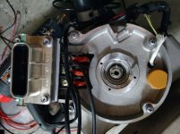
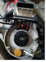
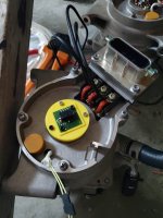
So I bought a Kelly 8080IPS with sine cosine input. I am trying to use it on the motor in the picture. The motor has a resolver in it. I was told resolver and sine cosine were the same thing, but now I'm being told other wise.
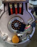
resolver.jpg

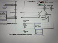
And here is the wiring diagram...
IMG_20200613_160839.jpg

The resistance on the 3 coils is 29 ohm, 29 ohm, 16 ohm.

I was thinking I could take a leg from each coil and connect to ground. Then take the 5V and attach to a leg on the 16 ohm, and take the 2 other legs from the 29 ohm, and 29 ohm and connect that to sine cosine...

Does that work? Any help is appreciated.

Thank you
Eric Ensley
 
That will not work. The resolver in that motor requires a sinusoidal drive signal in order to output a sin and cos signal. Your controller is designed for an RMB29AC that does not require a drive signal.

It is not clear from the manual if pin 16 on the controller outputs a sinusoidal drive signal, if it does you are in luck. Otherwise you will either have to build a drive circuit for the resolver or retrofit an RMB29AC.
 
oh the emotional rollercoaster!!!!

first line, will not work... OUCH.. damb it!!!!

second line.. it may work... lol!!

Thank you for the info... I am not an electrical guy. I was told a resolver was the same thing as a sine cosine...

Guess I'll just try it and then see if the motor spins or if the magic smoke comes out.

Eric
 
eric1565 said:
Guess I'll just try it and then see if the motor spins or if the magic smoke comes out.

Eric

What is "it" ?

Point 1) what you propose will not work, 100% guarantee and connecting 5V directly to the 16 ohm drive coil could possibly damage your contoller.

Point 2) *IF* pin 16 on the controller happens to be a sin driver output when you choose sin/cos mode then connecting that to one side of the 16ohm drive coil and the other end of the drive coil to ground may work. It sure isn't clear from the manual and it is probably a long shot. I certainly would try it without first putting an oscilloscope on pin16 to confirm.

Why risk blowing up the controller when an email to Kelly may give the answer you are looking for?

What will work is retrofitting an RMB29AC resolver to the motor, member coleasterling has already done that with the motor you have.
 
  • Like
Reactions: BSB
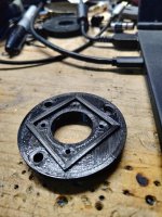
Got the sin/cos in. I am building a mount for it. I bought an aluminum bolt that I will drill to .16" dia hole for the 4mm magnet.

I got the connector that mounts to the sin/cos in. Now I need to wire everything up, and get my power supply hooked up to the speed controller.

I plan to run 160V to the speed controller once all is said and done. I will have 2 banks of 21S batteries. I will run in series to get 160V and I will pull the center wire to break it into 2 80V banks to charge. I plan on having a balancer on each 21S battery. Balancing the entrie pack will take place when I am charging. (21S 2P), and when running I will have a 42S1P battery.

IMG_20200629_214407.jpg

IMG_20200629_214351.jpg

IMG_20200629_214401.jpg

Eric
 
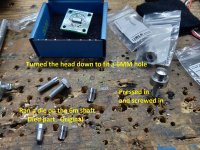
So after dilly dallying around, I got the RLS sine/cosine installed. I had to modify a few parts to get the magnets on the shaft.

I had to die the 6mm shaft of the magnet holder

I also turned down the head of a hex head bolt to stick into a 6mm hole. I pressed it in and screwed in the screw tight.

It all went together, now to fire up the speed controller and see if I can program the thing!!!!
IMG_20200724_214858.jpg

Here is the parts assembeld together. I did not get a pic of the die'd part screwed into the end of the shaft.
IMG_20200724_222826.jpg

Eric
 
HA HA, finally got it to spin. So here was the issue. My amplitude was off. I didn't know the formula and I was guessing at what they wanted. I was close, but off by about 20 pts.

Zero point=1023*((Min+Max)/2)/255
Amplitude=1023*(Max-(Min+Max)/2)/255

I was able to download all their software and run it. All that worked fantastic... well once I downloaded the driver for the USB device... I'm a knucklehead!!!

I was able to see the raw counts for the Sine/Cosie, and from there I got the zero point calculated. But like I said I screwed up the calc on the amplitude. I emailed Kelly and within 2 hrs I had a response. They gave me the formula and POW POW it spun.

So far only spun it on 20V. I plan to have 165V or so for the real deal. I am trying to now find a sutible rolling chasis to put this motor in. I was hoping to get a go-cart with suspension, or a golf cart.

Hopefully more to come!

Eric
 
kiwifiat said:
That will not work. The resolver in that motor requires a sinusoidal drive signal in order to output a sin and cos signal. Your controller is designed for an RMB29AC that does not require a drive signal.

It is not clear from the manual if pin 16 on the controller outputs a sinusoidal drive signal, if it does you are in luck. Otherwise you will either have to build a drive circuit for the resolver or retrofit an RMB29AC.

thank you, best regards
 
Back
Top