Build a controller for an Alta OEM motor and inverter?

thoroughbred

100 W
Joined
Apr 11, 2018
Messages
225
Location
virginia
I need suggestions of how to proceed towards getting an Alta motor and inverter up and running. I think the bike is designed like an electric vehicle with intertwined components run by proprietary software and circuit boards.
Alta OEM is 84S battery feeding Powerex/Mitsubishi IGBTs to spin a Fukuta motor.

I am learning that it is possible to bypass or spoof OEM control circuitry to be able to use electric vehicle drivetrain components in diy projects. I wonder if I can use any of these methods to get my Alta running. Examples include the Lebowski board, VESC board and openinverter.org boards used to get Tesla, Toyota and Nissan motors running. I think there are others like Axium but I think that is a complete unit?
20200720_092900.jpg
 
If it is a three phase BLDC motor, then the simple way, using KiwiFiat's Lebowski brain board, is to do it like in my HowTo thread linked in my signature (whcih also has links to other people's threads about doing it).

Basicallly what you would do is locate the gate drivers for the phase bridges, and disconnect their inputs from the rest of the circuit that controls them normally. This then allows you to control them from the brain board.

Then you need to find the phase-current monitoring devices, so you can use their outputs to feed to the brain board, so that it can monitor motor currents. If it doesn't have them or they're nto a compatible signal type, you'd have to install some on the phase wires.

There are some ohter connection details, but those are the critical ones.

To sever the connections, you might be able to just cut board traces, or you might remove teh controller chip entirely, or you might find the MCU reset pin and hold it in reset.


If it is not a 3phase BLDC motor, then you'd need a brain that is capable of controlling whatever type of motor it is.


So the first thing to do is determine the motor type.
 
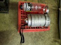
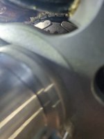
The motor is AC permanent magnet. It has 6 magnets on the rotor as seen in the poor photo. I think there are 36 windings on the stator.

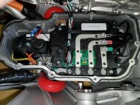
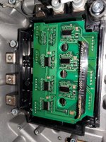
Here's the inverter.
The 3 cables on the right feed the motor and the smaller wires are from the "encoder" 20200721_081629.jpg
 
thoroughbred said:
The motor is AC permanent magnet.
What exactly does that mean? Which specific type of motor is it, and how many phases does it have?

You'll need to know that to find a brain you can use, because the brain has to know how to operate that kind of motor.


It *sounds* like you have a BLDC 3-phase motor...but I don't know.
 
ACPM was the description given by an Alta technician when asked what type motor it is.
https://www.dirtrider.com/2017-alta-redshift-mx-how-it-works/
I don't know enough to recognize a BLDC motor could be the same as a ACPM.

I assumed that the three cables feeding it indicates its a 3 phase motor. I'm learning as I go along, obviously :)

I have read that Fukuta in taiwan built the Alta motors. Fukuta lists its traction motors as Ac motors. Either induction motor IM or Permanent magnet synchronous motor PMSM

https://www.fukuta-motor.com.tw/en/download_D01.html

Pictures may or may not be helpful...
20200721_201302.jpg
20200721_201325.jpg
 
I haven't had any luck finding something that says what an ACPM motor is, or is equivalent to, or a "how it works" page.

If it's a PMSM, AFAIK that basically works like a BLDC (or is another name for one).

If it's induction, then I don't think the Lebowski brain can do it (but something else might).

The Lebowski doesn't know how to read a resolver or anything other than 3 hall sensors, but it does operate sensorless. And you can add hall sensors to any motor, though some may require more work to get them in the right spot than others.
 
Looks like a synchronous permanent magnet 3 phase motor to me. Sometimes called a 3 phase BLDC motor.

What do you want to use the motor and inverter for? Any reasons to use them besides the fact that you have them? Realistically, I don't think the OEM Alta motor and inverter are very useful outside of the Alta ecosystem. There are several off the shelf motor and inverter options that can produce similar power without needing 2 stage gearing or such high voltages. They may not quite match the weight of the Alta system, but they will be much easier to implement.
 
I have a test mule Alta motorcycle that I would like to get operable. It's a prototype bike and the logic chips won't communicate with the Alta software ecosystem that is currently available. I have all the hardware but can't talk to the software so I'm exploring ways of getting around this, if possible.

It seems like I'm in the same boat as someone who buys a wrecked Tesla and wants to utilize the hardware outside of the Tesla ecosystem.
 
Since the motor has permanent magnets and doesn't have hall sensors, I'm leaning towards this being a PMSM motor rather than a BLDC. They are pretty similar, apparently

https://www.researchgate.net/post/what_is_the_difference_between_stator_windings_of_BLDC_and_PMSM_motors

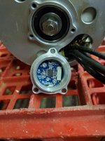
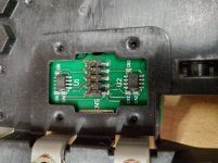
Here is the actual position sensor on the motor. The website states that the applications are AC/DC motors and BLDC motors. https://ams.com/as5134#tab/applications

I guess a place to start is to see what controllers can utilize this type of position sensor. I have a Mobipus controller that describes itself as a PMSM controller in the manual. It also has "encoder" parameters so maybe I can try to get it spinning?
 
thoroughbred said:
Since the motor has permanent magnets and doesn't have hall sensors, I'm leaning towards this being a PMSM motor rather than a BLDC. They are pretty similar, apparently

https://www.researchgate.net/post/what_is_the_difference_between_stator_windings_of_BLDC_and_PMSM_motors

Here is the actual position sensor on the motor. The website states that the applications are AC/DC motors and BLDC motors. https://ams.com/as5134#tab/applications

I guess a place to start is to see what controllers can utilize this type of position sensor. I have a Mobipus controller that describes itself as a PMSM controller in the manual. It also has "encoder" parameters so maybe I can try to get it spinning?

The AS5134 data sheet shows UVW outputs which are HALL signals so you can run this motor with a Lebowski controller as it is a permanent magnet motor. As amberwolf suggests the best option would be to identify the existing gate drives and current sensors then you only need to replace the brain function of the existing inverter.
 
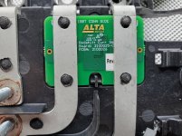
Here's the current sensor straddling two busbars

20200815_064203.jpg

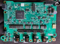
Here's the pcba with the Texas instruments chip watchng over. I need to read up on how to identify gate drivers.
Maybe this sheet shows where the MCU could be deactivated? https://www.ti.com/document-viewer/TMS570LS10106/datasheet/device-characteristics-spns1418943#SPNS1418943

20200815_064221.jpg

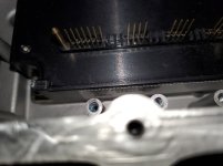
The pcba mounts onto these pins going into the IGBT module. http://www.mitsubishielectric.com/semiconductors/php/eTypeNoProfile.php?TYPENO=PM300CG1C065&FOLDER=/product/powermodule/ipm/g1_series

https://www.ebay.com/itm/Alta-Motors-IGBT-MODULE-CONTROLLER-REDSHIFT-REV-7-2100012-02/202919400323?hash=item2f3ef05383:g:BqAAAOSwHgdeXXHT

Mine is labeled as a Powerex module but it seems that company sold off to Mitsubishi...

20200815_064311.jpg

THe igbt module is bolted to the motorcycle frame and is watercooled
 
Are these the gate drivers? I searched A4506 gate driver and these came up Avago/Broadcom HCPL-4506

https://www.digikey.com/product-detail/en/avago-technologies-us-inc/HCPL-4506-500E/516-2718-1-ND/3909215?utm_adgroup=Optoisolators%20-%20Logic%20Output&utm_source=bing&utm_medium=cpc&utm_campaign=Shopping_Product_Isolators&utm_term=&utm_content=Optoisolators%20-%20Logic%20Output&utm_id=bi_cmp-306009173_adg-1296324335221985_ad-81020291355332_pla-4584619894822833_dev-c_ext-_prd-3909215&msclkid=59f886f285ae1becfedbd9c542cea3ae

https://udvabony.com/product/a4506-gate-drive-interface-optocoupler/?__cf_chl_captcha_tk__=6044359a617d9c36e6b7446a8f38beac95bce30d-1597490307-0-AdZsxCLN9YRwMI9uEFfvCqfQlrv0tHr7azp5WtJL3kLBEkZTcQdeuqLQeH5nKl8t1nMBR5jdicJS_Nc-0Uz3YVFjwSQrMT5O8bNz4-iSPyiGa0-ikXT00RnslbJFoEcCoc2NdJW_39iAFGmmMdl1Ktp9h4Z11nx7nKr_JVLoHdgpx1kgHj-oTSDVI8XwQkDnfi0MK0Z5OAoLohq3h_EH7BNS2FTvGxCI7v2TNhuHUyKQtaL4PNJGsQ1t5CCWWt7xtSBj62VOl5rgMSeR41AkTlGIzPUNfK0ZKdJDMssYoOX5uQilkTjuWDi2BQxb-AW4TFaqkUMtrz597Aw2P65i9uzkwUaHfdX_AfbPHVSLZGp-AeJffvqwQecVYsVyNC05tetowTf666lasfbMFOWhGgajx7rSmvjLe93dF5pCExeqLl88O8QQaD3RsQivZu2cav8QODF-wnsni8cEU1mX4zH79HfaRRbr4WgsY7yPw3cYIKD6ZRuwI3NPFM4MiEaNeDREJU0-MmK7gWtZKts1zJMm8or0BBCsngen6l8kTQsEf9SS9brB50zG66dPxkr19W0vLbQH0QRqM92w-R46PdjxWYAF3wIkqhzmay4ixSK1
 
Your PM300CG1C065 IGBT brick has 6 integrated gate drivers for each of the 6 switching IGBTs in its 3-phase bridge. Those Avago parts are optoisolators used to send signals to those integrated gate drivers and provide galvanic isolation from LV to HV. The 4 transformers along the bottom of the driver board are used to power the integrated gate drivers. 1 transformer is used in common for 3 low-side drivers and the other 3 transformers are used per each high-side driver. You need to ensure all 3 high-side drivers are isolated from everything else as each high-side driver is referenced to its respective emitter, which is the PWM'd phase output.

Your IGBT brick also provides a fault signal output per IGBT. This is probably overcurrent and overtemp detection, but not desat detection. Overcurrent detection should be sufficient according to their implementation.

A number of optoisolators on your driver board are used to transmit this fault signal from the HV side to the LV side. Those are probably the smaller 4-pin optoisolators. You can see that all low-side faults are logic-OR'd inside the IGBT so there's only 1 low-side fault isolator.

From left to right, I believe your optoisolators carry the following signals:
1. Low-side desat fault detection
2. W-phase low side PWM
3. V-phase low side PWM
4. U-phase low side PWM
5. W-phase high side PWM
6. W-phase high side fault detection
7. V-phase high side PWM
8. V-phase high side fault detection
9. U-phase high side PWM
10. U-phase high side fault detection

Nice photos showing Alta internals. I'm always interested to see how automotive drives are designed. I see they used a Hercules MCU which provides ISO26262 functional safety features.

Also, be careful with that rotor position sensor. If it's factory aligned, taking the sensor off will mess with the alignment. If it's not factory aligned, you can align the sensor in software using the absolute angle interface. You should double check the alignment before relying on any UVW hall outputs. If Alta used the absolute angle interface (which is good engineering), then your UVW output could be totally bogus.
 
excellent contributions here that i appreciate.

it just dawned on me. I also have a working Alta and the diagnostic software. the raw data might reveal a bunch of things about the inverter and motor, like hall signals vs something else
 
Chances are your inverter and encoder use the absolute angle interface. It's SPI. The upper left-hand connector labeled ENC has 2 labels, RACS and RACLK which are typical SPI signals. I think VESC has some kind of support for ams encoders but if it doesn't it's possible to write some code to read the encoder. You want firmware that can automatically align the encoder properly to the motor's reference frame; motor performance is very sensitive to proper alignment (especially at high speeds and in the field weakening region).

If you want to know more about the current sense scheme you'll need to take pictures of the underside of the current sensor board.

As for the diagnostic software- it's probably more trouble than it's worth. The main interfaces of any motor drive are all basically the same.
 
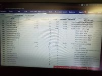
I haven't taken the chip out of the encoder housing yet but I did hook my other bike up to the laptop to look at what data points are being read20200823_073612.jpg

Items 383 to 391 mention motor parameters and 389 is motor position and says 256/rev in the descriptor. Does that confirm absolute angle timing? The software has a tab that brings up a timing routine but idiot enter that area yet as my bike runs great.
 
The SPI interface along with the motor sensor offset parameter indicates that the sensor is being used in the absolute angle mode, which makes sense- you really want as much angle information as possible for high-performance motor control. There's a reason you only see absolute encoders and resolvers in these applications. Unfortunately the angle offset value is not being reported (since the value column is empty). This value is probably unique for every motor-encoder pairing, because there are several places where angular misalignment can be introduced during manufacture-

1. Encoder chip to motor housing alignment
2. Stator to housing alignment
3. Rotor to encoder magnet field alignment

Are you sure you can't just sniff the CAN bus and reverse engineer their messaging protocol? You could just run the entire inverter from your own ECU that way.
 
I played a little with the working bike to see what happens to the motor position data when I spin the rear wheel.

The number goes from 0 up to 65,535 then again to 0. The description field says "Accumulated motor position, 256/revolution"

256 x 256=65536 Not sure what that means....

I guess the next step is to figure out how to power up the encoder chip and see If I can read any output
 
fictivedesigns said:
Chances are your inverter and encoder use the absolute angle interface. It's SPI. The upper left-hand connector labeled ENC has 2 labels, RACS and RACLK which are typical SPI signals. I think VESC has some kind of support for ams encoders but if it doesn't it's possible to write some code to read the encoder. You want firmware that can automatically align the encoder properly to the motor's reference frame; motor performance is very sensitive to proper alignment (especially at high speeds and in the field weakening region).

]

If you want to know more about the current sense scheme you'll need to take pictures of the underside of the current sensor board.

As for the diagnostic software- it's probably more trouble than it's worth. The main interfaces of any motor drive are all basically the same.

I'm still inching forward. Heres the backside of the current sensor20210301_191457.jpg

Also here are the six gate drivers under the igbt cover 20210301_192820.jpg

Now that you have shown me what many of the components are, I need to figure out if any or all can be utilized going forward. Hopefully it's not all or nothing...
 
It's a parallel tooth Surface mount Permanent Magnet motor also called SPM motor. It's a BLDC motor with high voltage and and low current version and the power density is very high. The increased voltage helps it to maintain the torque into very high rpm.

The Sensor in the photograph is simply a hall sensor (if I'm not wrong) that's look like a second generation hall sensor, in 2017 Global microelectronics engineering company, Melexis, has announced a new second-generation resolver motor position sensor based upon its proprietary Triaxis Hall magnetic sensing. The new single IC solution MLX90380 is compatible with any brushless motor - including Permanent Magnet Synchronous Motors (PMSM) and Brushless DC Motors (BLDC) - thanks to its ability to measure the absolute angle. It is suited to the automotive applications.

The current sensor is also a similar current sensing methode (https://www.melexis.com/en/product/MLX91205/90kHz-IMC-Hall-Current-Sensor).

I hope this can be driven using any off the shelf motor controller (inverter) with hall sensing (can be either sine or cosine).
 
I have same setup. Mine is probably newer inverter wise. I’ve been waiting to resolve my sevcon setup before I start tinkering with the Alta rabbit hole. Interested in if you powered up yours. I think the new stark varg bike might hold the key to getting it going. Their video depicts a motor similar Alta’s motor
 
Back
Top