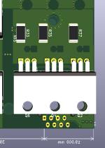
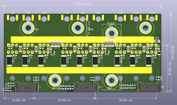
I just had a crack at a through hole power stage

mxlemming

100 kW
Joined
Jul 17, 2020
Messages
1,120
Hi all,

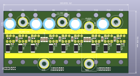
It still seems to be the rage to make up through hole power stages still, so I thought I'd have a go at it myself. All the cool kids are doing it. Right?

Started it at 5pm this afternoon and got this far just before dinner at 8:30, so not much time invested so far.

If anyone is interested, I'll complete it and push it to github. Just thinking I'll add a PICOFLEX ribbon connector to get all the connector gubbins. Might also add some footprints for snubbers.

With a decent FET choice, you could easily have 200A continuous, 400 or so peak I reckon.

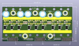
100x 50mm, so pretty damned tiny. Need to add more electrolytic caps though! A row of 16mm OD caps would only increase the total size to 60mm or so, so still not huge!
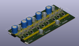
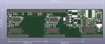
ISOMETRIC.PNG
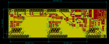
TOP VIEW.PNG
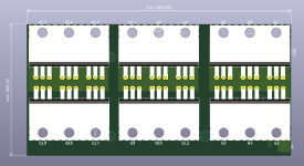
BOTTOM VIEW.PNG

Layout as below, scheme for routing and returning gate signals very neatly
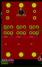
TOP LAYOUT.PNG
BOTTOM LAYOUT.PNG
INNER LOWER.PNG
INNER UPPER.PNG

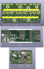
Connector in, all drivers, control, opamps on another board.
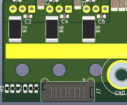
PicoFLEX input.PNG
 
I'd go ahead and put it out there, because there are people that might build things like the Lebowski controller variants that need a powerstage.

(If I could reliably build stuff completely "from scratch" anymore, I would do it...but I went for hacking the Lebowski brain onto the Honda IMA powerstage, though I have yet to completely finish that project).
 
Where can I get one of these Lebowski controllers? Do I need to.. ask Lebowski nicely? The guy who used to distribute them prebuilt seems to have stopped.

Also, they don't seem to support low side shunts, only phase shunts. Is this correct?
 
It's open source if you want to build your own brain board and flash the chip (look thru lebowski's posts for his thread about that; you could even modify the code to suit your needs), or Kiwifiat makes a small SMD brain board (that's what I got last year). BobC had a thread for building the thru-hole brain board, I think, it should have gerbers and such to have PCBs made if you like.

It doesn't monitor battery current, just phase currents. I suppose if you needed to also monitor battery current, you could alter the code to do that (but it needs the phase currents for FOC).
 
Made a driver board to go with it. Not quite finished, but basically it's now a case of choosing where to put connectors, and I am considering a comparator to catch over voltage conditions. INA240 opamps, Infineon 600V gate drivers with 2.3A drive capability (plenty for through hole FETs given the slow switching requirements...) a seperate power ground for each phase and hypothetically shoot through protection + undervoltage lockout.
Driver Board layout.PNG
Driver Board.PNG

Connects to the power board by PicoFlex IDC ribbons at the moment. Considering making them stack... But not so sure about that.
Power Board connectors.PNG

Extra capacitors can be fitted side on if wanted, just scrape off a bit of the solder mask:
Side view Capacitors.png

I spoke to KiwiFiat about a Lebowski, and he made me a reasonable offer, problem is, it only supports phase shunts, which means I'd have to mod this whole thing... which is quite a piece of work. Looking into that, or a "dual fit" option. I much prefer ground shunts, since they can be used with any voltage without expensive and/or bulky inductive sensors.

Definitely not in a state of mind to be reverse engineering Lebowski's assembly code. Yet. I kind of really want one though...

On the off chance that Lebowski reads this, is it completely unrealistic that the code could handle low side shunts? Obviously there are clear problems with low side measurements, such as... the current reading zero half the time, and having to base FOC off two phases only at high modulation etc.
 
Design is now up on Github. Nearly ready to order. Just need to add part codes and values to the driver board for LCSC and rearrange the pinout for Lebowski controller input.

https://github.com/davidmolony/MESC_MODULAR.git

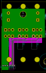
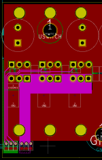
It's a bit of a hack, but there are now phase shunts. They live under the FETs.
To use them, have to slice through the white line and fit the shunts on top.
Phase shunt setup.PNG

The phase shunts are optional fit, and can be enabled with the resistor pairs R30, 40, 42
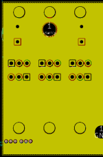
Top view.PNG

Snubber circuit added... 3.3nF and 2.2R resistors. Basically all good to go...

Wonder how this will turn out. Ringy dingy? Bouncy? Best case, it looks like Peter's board. Worst case, I create weapons grade ringing!
4.7 ohm resistors on the gates. Going to put much larger ones on the driver board (5ohm plus the 5 ohm on the gate drive), for an effective resistance of 35 ohm total/FET), with an optional fit reverse diode. This board, contrary to my SMD board is going to switch nice and slow.
 
Back
Top