More kV = More power? What are the trade-offs?

swbluto

10 TW
Joined
May 30, 2008
Messages
9,430
[This post had incorrect assumptions about how the typical motor was wound when the kV was changed. As such, the initial starting torque is different as shown in my next post and so is the starting heat.]

If you take a motor and wind it half the amount originally, the kV doubles while the resistance halves. This reduces the torque constant by half, so the torque at 0 rpm will remain the same at a given voltage since the halved resistance implies twice the starting current. This and all future discussion assumes no current limiting.

So, in essence, you don't really seem to change the starting torque. Made sense, there's no such thing as a free lunch, right?

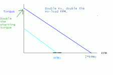
But what I didn't realize is that the higher kV motor version would have a higher peak power. At a given voltage, the doubled kv will have a doubled no-load RPM and the torque at half the no-load RPM will be the same as the torque of the original motor at half of its no-load RPM since the torque is a straight line from the initial torque down to zero torque at the no-load RPM.
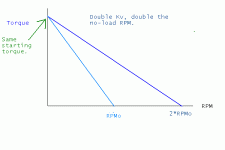
torqueKvRelationship.GIF

Roughly speaking, power = torque * RPM and since the torque at any RPM greater than 0 is higher for the doubled KV motor, the power of the higher KV version of the motor will be higher at a given RPM.

This is quite fascinating, because I originally quite kindly thought those who chose the kigher kv versions of a given motor were fools (Surely lower kV versions would've been easier to gear?) but now I can see why such a preference exists. This also goes quite a ways to explain why these high-kV outrunners are oddly as powerful, if not more so, as the much lower kV and much bulkier hub motors.

However, this extra power doesn't come without a hitch. Generally speaking, you need a higher reduction to make it fit within the same speed range which can reduce efficiency and output power if you start breaking it up into multiple stages. Also, the heat of the higher kV motor will be higher at a given RPM. At 0 RPM, the doubled kV motor has half the resistance and twice the current, but the heat equation is I^2*R, so the heat at 0 RPM is double. Since the higher kV motor generates far more heat at the rpm by which the lower kV motor is running at no-load, it's clear the higher kV motor will run hotter at a given rpm.

But, let's gear it for the same speed range. That is, let's say you simply double the reduction ratio for the higher doubled kV motor to get the same no-load speed (not to be confused with the no-load RPM). Than at the no-load speed, the higher kV motor will have slightly higher cogging torque and eddy current losses since its running at a greater rpm, so the no-load current of the higher kV motor should be at least as great if not greater than the lower kV motor. Let's see... I^2*R - it seems to be a toss up but I think they'll probably be fairly close to each other (Higher kV motor will have a slightly higher no-load current, but half the resistance - If the no-load current is 1.414 or the square root of 2 times greater than that of the lower kv motor, then the no-load heat will be the same). So, at 0 RPM, the double higher kV motor will generate twice the heat and both motor may have similar heat outputs at the no-load speed. So, in essence, the higher kV motor will run hotter.

Summary: higher kV versions = more power. Cons - greater motor heat and greater reductions generally needed. If geared for the same speed, the worst case is twice the motor heat at 0 rpm and the gap decreases to much closer motor heats at speed.

Are there any other cool principles that I haven't figured out yet that may be awesome to know?

I think this may have changed my strategy to get the highest kV without necessitating more reduction stages than necessary. However, not only does a higher kV motor produce more heat, but it also has less thermal mass (it has less windings and the motor may be shorter) to absorb that heat so I may have to be more careful with the motor temperature.

Anyways, this principle is mainly to be applied to different kV versions of the same motor. Like the 6-turn and 10-turn versions of the astro motors, and the 130 kV and 200 kV version of the giant HXT 6-7kW motors. This explains why hobby-city rates the power of the 130 kV version at 6 kW while I believe it rates the 200 kV version at 7 kW.
 
My throw at this is,

You don’t decrease impedance by half winding a coil, you increase its core size thus allowing more current into the circuit. Ideally one would need = inductance and lower impedance of the said coil to increase N (force). mFr magnetic field reactance will then apply to the result of the said coils specifications delivering velocity accordingly or (N) newtons.
 
Miles said:
Crikey! Where have you been? :mrgreen:

For a given stator size, doubling the Velocity Constant reduces the winding resistance by a factor of 4.

Ergo...........

I'll need to understand "stator size".

My understanding was that the velocity constant was increased by simply decreasing the number of windings (instead of winding a wire eight times around a rod, it's wound 4 times; the number of wires wound around the rod doesn't change), and that this corresponded with a shorter motor (or just less filled copper space). However, if the fill volume remains the same (which I think corresponds to "stator size"), then that'd make sense.

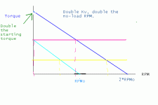
If that's the case, then, the doubled velocity constant motor would have an initial torque twice as high as the lower kV motor and 4 times the heat at 0 rpm (I*2*R). It looks like the higher kV motor would have higher power output pretty much everywhere over the speed range and more torque everywhere with the same voltage. Here's a graph for everyone's viewing pleasure.

torqueKvRelationship2.GIF

I was looking at the 180kV and 130kV versions of the popular 80-100 HXT at
http://www.hobbycity.com/hobbycity/...0-100-A_180Kv_Brushless_Outrunner_(eq:_70-55)
and
http://www.hobbycity.com/hobbycity/...0-100-B_130Kv_Brushless_Outrunner_(eq:_70-55)
and they don't mention a size. They "look" about the same though, although I think they just purposely used the same image. Do you think the fill volume is about the same? Interestingly, the 180 kV is at 17 mOhm and the 130 kV is at 32 mOhm. (130/180)^2 * 32 = 16.69.... it appears the fill volume does remain the same. So, not only do they reduce the number of windings, but they increase the number of parallel wires to wind on a given pole to fill the space. So, I guess you're right Miles, that generally a lower kV motor version has a squared relationship with the resistance to the number of windings in practice.
 
Oh yeah, interesting side note, if you geared the motor for the same no-load speed, then it appears the tire's torque would approach 4 times than it was originally at a stop. This suggests...

If you want huge torque and have little concern for speed, go with a higher kV version of a motor. This is if you think the heat will be manageable... (Which on astro motors, appears to be so. I heard the practical limits of the motors was like 400-450 degrees fahrenheit?). Particular applicable areas would probably be "rock climbing bikes" and "trials bikes". On the down-side, this would severely increase the heat on the controller which a typical ESC may not take so kindly to.
 
Keep coil inductance as part of your equasion.

Resistance is impedance measured in ohms. inductance can be amounted by the amount of turns in a coil. If you take the turns out of a coil to decrease impedance resistance and you decrease inductance. This will take away reactance. This will either blow your motor or controller. Lets say we leave the winding turns in there and increase the coil core or parallel another core winding this will give you your decreased resistance impedance, draw more power and still give you plenty of magnetic field reactance to push the motor without creating too much more heat over the winding and or controller fets. Withoiut reducing your winding you give energy and power a place to sink its teeth into.

Taking the tuns out you are creating a short wire that does little. Make the turns thicker.
 
Good note for those who are (re-)building their own motors. Less reactance = higher current = "blows something up" - if you have a weak controller, like most ESCs, then a lower kV version may be sensible. If you have an awesome controller, then I probably wouldn't care unless motor heat was a limiting factor which I doubt. But even then, I'd have to investigate in more depth. At speed, the motor heats shouldn't be that far off, but they'll start to approach the max difference in heat at 0 rpm as the motor slows down (Like on hills and stuff). In which case... I'd probably just do a graph-by-graph comparison using my simulator on a case-by-case basis to evaluate. I evaluate motor heat before buying any motor, anyways.

I'm just a buyer though. All I have to look at is different kV versions of a given motor, mainly. I'd even go far to say I'm more technical than the average buyer of these kinds of motors, which probably means looking at anything more would probably be too complicated for the typical buyer to evaluate.
 
You make a magnetic field by pushing energy into a coil right. By this art one converts energy and power into a magnetic field. The more energy and power you put in there the larger the magnetic field until the the energy arcs or melts through the winding insulator due to heat. By reducing coil count you reduce the magnetic field a coil can possibly make. To a small degree maybe a few turns you may yield results at the expense of surface area energy can make a magnetic field and by decreasing impedance resistance you create more heat yeilding no viable MF.

Ohh I get you.

as long as the resistance is not too low any controller can make the grade.

Like you cant run 4 ohm speakers on an 8ohm designed amplifier but you can runb 8 ohm speakers on a 4 ohm designed amplifier. A big controller vs a small motor can work providing pwm and or load doesnt sing or pull it down to the motors death but a big fat motor on a small controller risks burning out the controller.
 
The torqe a motor produces is a function of the number of winding turns times amps (amp-turns).
For a given motor size, if you double the number of turns, you'll get double the torque for a given amount of amps, and the no load speed will be half. Assuming the same volume of copper, the resistance of the windings will be 4x higher, so to get the amps to flow, it requires more voltage.

Think of a winding made of two parallel strands and, for example, 10 turns. If you reconfigure the ends so they are in series, you've doubled the number of turns. The dc resistance of the series configuration will be 4x the parallel configuration.

There's no free lunch. For a given motor volume, you can get about the same power output with either configuration, but at different voltages. The idea is to maximize efficiency. Too far to one extreme, and the resistance losses in the windings become excessive. Too far to the other extreme, and the losses due to high rpm (core losses + friction + windage) become excessive.
 
swbluto said:
My understanding was that the velocity constant was increased by simply decreasing the number of windings (instead of winding a wire eight times around a rod, it's wound 4 times; the number of wires wound around the rod doesn't change), and that this corresponded with a shorter motor (or just less filled copper space). However, if the fill volume remains the same (which I think corresponds to "stator size"), then that'd make sense.

Why on earth would you not want to maximise copper fill? :?

As fechter said, if you want to increase Kv, you reduce the number of turns and increase the wire diameter or use multi-stranding, to achieve the same fill.

Changing the termination between Wye and Delta has pretty much the same effect as changing the number of turns.

Neither way gets you more continuous torque, unless your batteries can't deliver enough amps at lower values of Kt.
 
Miles said:
swbluto said:
My understanding was that the velocity constant was increased by simply decreasing the number of windings (instead of winding a wire eight times around a rod, it's wound 4 times; the number of wires wound around the rod doesn't change), and that this corresponded with a shorter motor (or just less filled copper space). However, if the fill volume remains the same (which I think corresponds to "stator size"), then that'd make sense.

Sorry, it might have been better to have written "stator core size".

Why on earth would you not want to maximise copper fill? :?

As fechter said, if you want to increase Kv, you reduce the number of turns and increase the wire diameter or use multi-stranding, to achieve the same fill.

Changing the termination between Wye and Delta has pretty much the same effect as changing the number of turns.

Neither way gets you more continuous torque, unless your batteries can't deliver enough amps at lower values of Kt.

As stated, I'm not building or rebuilding a motor, doing so really sounds like boresville. So, why I, ME, MYSELF wouldn't want to maximize copper fill is not a question I would ask myself - producers, on the other hand, would end up using less copper which means less copper costs to produce the motor. It also could mean a smaller motor, although it appears they don't change the motor casing or size. Given most motors are manufactured in China, it's understandable. :wink:

Also, as a part of that not building or rebuilding, changing the termination is not an option unless the supplier offers it. Even so, it's good to know equivalences as part of this understanding everything quest. Thanks for the comparison.

As to continuous torque..... I don't know that the continuous torque rating isn't changed when kV is changed while maintaining maximum copper fill. To maintain the same amount of torque, the double kv motor would have to pass by twice the current which means four times the heat but the resistance is also a fourth - so the copper-loss heat would remain the same. Since copper fill is maximized, the thermal mass remains the same. Yeah, I guess you're "about right" - I still don't know how the losses other than copper would figure into the equation, but I assume copper-losses by far the most significant factor in the continuous torque limit. I guess to increase the continuous torque limit, you'd need to reduce resistance(silver wire, and/or, superconductors), increase the fill and/or decrease the "thermal resistance"/"increase the cooling effectiveness". For quasi-bursty-continuous limits like going over finite sized hills, it seems thermal mass would also figure into the equation.

I don't really think I'm too affected by the continuous torque limit though. Well, with a high-temperature motor like an Astro, I don't think I would be. :D
 
Yes, it'd be nice to have data on the magnitude of iron losses. I know you, Miles, gave the polynomial relationships once but I don't remember anything about the typical magnitudes of each.

From the continuous torque limit remaining the same principle, I hypothesize:

[Okay, I'm still evaluating this claim. Don't be too harsh.]

Claim:
The copper-loss based heat is the same regardless of kV at some given output. So, in essence, going up a hill will generate about the same amount of heat at the same speed since the same amount of torque output is needed to maintain that given speed. So, there's no way around it by changing kV (And that's the motor's limiting case in my opinion for regular transport, especially more important for the Turnigy type of motors.).

Example-based reasoning - Still evaluating... The torque output of the motor is the same as they generate the same amount of heat, but what about the motor RPM and how would that affect the torque at the wheel? The following graph depicts motor RPM.

torqueKvRelationship2sameTorque.GIF

The motors have the same torque at an RPM that has a constant gap between the two. For the double-KV motor example, this RPM gap corresponds to the no-load RPM of the original motor, RPM_o. The ratio between the RPMs vary between infinity to 2. Let's pick some awesome number, like 4. To gear it for the same speed, the reduction would have to be 4 times as great (And who would do that? Let's call it an example), meaning the torque at the wheel is actually 4 times as great for the double kV motor than the single kV motor meaning the double kV motor still has some tire torque left-over - it accelerates and rests at a higher top speed. So, actually, it seems this example violates the principle I had - I failed to distinguish between tire torque and the motor torque, and it appears the higher RPM that a constant torque corresponds to for the higher kV motor means there's more power left over, and so the higher kV motor settles to a lower motor torque (A higher tire torque, still, to maintain a higher speed) and generates less heat while the vehicle moves faster? Vut???

Wait... this seems to suggest a higher kV motor should run cooler with the appropriate gearing (it's geared for the same top speed), ignoring iron losses, when encountering things like hills while also going faster. Hmmmm... this seems counter-intuitive, so I want "evidence" to support this reasoning - I'll go check my simulator.
 
Ok, so I used typical values - I set the current limit to essentially infinity (No current limit), set the battery voltage to 48 and made the battery's internal resistances practically none (.00001). This is on flat land. Any other values that you want to know, just ask.

For the example motor, I chose 100 kV and .1 ohms. The gearing ratio was set to 12 to get a speed of 29.6 mph. Generated heat is 140 watts while thrust is 59.5 newtons.

I then changed to 200 kV and .025 ohm. The gearing ratio was set to 24 to get the same designed top end speed. Output was 30.6 mph, generated heat of 116 watts and thrust is 62.5 newtons. The principle seems to be holding for flat land!

Let's try a hill. Let's say 10%. We'll keep the gearing and motor values the same.

100 kV, .1 ohm, gearing ratio = 12. Output - speed of 27.1 mph, heat of 398 watts, thrust of 162 newtons.

200 kV, .025 ohm, gearing ratio = 24. Output - speed of 29.4 mph, heat of 235 watts, thrust of 169 newtons.

Woah! It looks like higher kV motors are also more powerful while also producing less copper heat! I have a feeling that iron losses will start to become more important at some RPM, though... and we'll then meet the optimum point/range. In the simulator, the "No load current" symbolizes iron losses and other motor losses, but this will change depending on the RPM and thus the kV. My above simulations didn't take this into account as the no-load current wasn't changed.

Of course, more stages reduce drive efficiency, so just the highest kV without needing a change in stages seems to be best.
 
fechter said:
For a given motor volume, you can get about the same power output with either configuration, but at different voltages.

That's the problem, though. Many of the "performance mongers" are going to use the maximum voltage possible with pretty powerful batteries (like 200 amp capable and above), which makes the higher kV motor more powerful at that limit.
 
swbluto said:
In the simulator, the "No load current" symbolizes iron losses and other motor losses, but this will change depending on the RPM and thus the kV. My above simulations didn't take this into account as the no-load current wasn't changed.

Ok. Let's see:

Bearing losses are proportional to RPM
Hysteresis losses are proportional to RPM
Eddie current losses are proportional to RPM²

So, the no-load current will be a constant for bearing losses and hysteresis losses but will increase with rpm for eddy current losses. Right?
 
Miles said:
swbluto said:
In the simulator, the "No load current" symbolizes iron losses and other motor losses, but this will change depending on the RPM and thus the kV. My above simulations didn't take this into account as the no-load current wasn't changed.

Ok. Let's see:

Bearing losses are proportional to RPM
Hysteresis losses are proportional to RPM
Eddie current losses are proportional to RPM²

So, the no-load current will be a constant for bearing losses and hysteresis losses but will increase with rpm for eddie current losses. Right?

Let's try to make sense of the bearing and hysteresis constant losses.... doo doo doo...*thinking*

Ok, I'm puzzled. I don't understand why the no-load current would be constant for bearing and hysteresis losses if both of those losses are proportional to RPM and you're comparing a higher kV motor running at a higher RPM near the no-load speed and a lower kV motor running at a lower rpm near the no-load speed. (I'm using no-load speed to indicate the speed of the wheel.). Oh, wait, let's see... so the bearing power losses are proportional to RPM, and a higher RPM with the same no-load current (same torque) is proportional to power. Ok, I see.

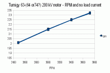
Yes, that makes sense. What are typical power losses with RPM? I could just spin up my motor at no-load and check for different voltages. I think the ESC will only activate at 10 volts and the my power-supply will only go upto 18 volts, so I'll have a limited testing range, but it seems appropriate enough to get a general idea. *testing underway*
 
I found out my voltage range was more limited than I thought. The ESC will turn on at 10 volts, but it won't run until it has above 12 volts.

RPMandNoLoadCurrent.GIF

Anyways, it appears to be linear as you thought. For this particular motor, doing a linear regression, it seems

No-load current = .000251*RPM + 1.391.

RPM Predicted No load current
1000 1.64
2000 1.89
3000 2.14
4000 2.4
5000 2.65
6000 2.9
7000 3.15
8000 3.4
9000 3.65
10000 3.9
11000 4.15
12000 4.4
13000 4.65
14000 4.91
15000 5.16
16000 5.41
17000 5.66
18000 5.91
19000 6.16
20000 6.41
21000 6.66
22000 6.91
23000 7.16
24000 7.42
25000 7.67
26000 7.92
27000 8.17
28000 8.42
29000 8.67
30000 8.92
31000 9.17
32000 9.42
33000 9.67

It looks like the no-load current increased by 1.2 amps with every increase of 5000 RPM. In my example, that would increase the waste heat for the double kV motor by 1.2 * 48 volts ~= 60 watts? Still doesn't look like a bad trade-off for hills (235 + 60 = 295 watts as opposed to 398 watts for the lower kV motor) in my example , but it appears the motor will be slightly hotter when running at speed - that doesn't matter, though as hills and other high loads are what matter since they're the limiting cases.
 
I understand the op better now.

As I see it there is correlation to RPM however to load not torque but there is no load mentioned in the graph rather that there is no-load. Yes there is torque but load varies from one scenario to another.

One can certainly drive a thicker coil with lower impedances with a lesser controller as long as the inductance is still viable and the gearing of the motor is made right.

On my brushled motor on a 24" wheel at 36v the motor winds up fast and has excellent torque and adequate speed and has lived a very long time where on a 26" wheel the motor still delivers torque in a given RPM range but suffers from much heat and burnt out Taking turns out of that motor would decrease impedance but would certainly not be the solution to the problem. Increasing RPM does by reducing the load by means of correct gearing and yields better torque, increasing the thickness of the windings would as well. Providing the fets can take the lower impedance of the coil there is more power to be had.

Stator ratio has a lot to do with this as well but not in this case as both motors have the same stator size. Further looking at the specs of the motor it does describe the more powerful motor has less wire turns but it also describes that the more powerful motor weighs the same, which one would they have us believe. The price is the same but I would agree that the way in which they have increased the motors power is not the bee's knees approach. The idle power consumption has increased too much IMO to gain this extra power and even if the motor runs in specs I believe the lower power motor would be more efficient and have better power at a few more volts than the higher powered motor if indeed the coil width is equal on the more powerfull motor.


Do they increase the width of the winding is the question or have they just reduced number of windings within specs to gain an inefficient advantage.
 
I thank miles for the motor graphs but I admit I have a really hard time relating it to ebike use. I find these types of graphs that graph it over speed or RPM to be more intuitive for ebike use. Here's one for the 6-7kW 130 kV turnigy and 180 kV turnigy motors just as a practical example. The controller and battery resistance were practically zero to show the motor's performance alone and the voltage is 48 volts. This is unrealistic and the output power will be lower due to the controller resistance and battery's internal resistance, but it gives a good idea of the comparison between the two.

View attachment 180kvOutrunnerGraphresized.png

View attachment 130kvOutrunnerGraphResized.png

I'll possibly comment on these in a later post when I can see the graphs retrospectively.
 
Here's two different motors that seem to be different "versions" of the same motor, but it appears that second number of its name (As in the 64 of 63-64) differs and I think that indicates a different motor length and, thus, "copper fill length" and thus copper fill volume. So it appears some of these different "versions" actually use slightly different motor cases and aren't just simply wound a different amount of times.


63-74 form, 170 kV.
http://www.hobbycity.com/hobbycity/store/uh_viewItem.asp?idProduct=7870&Product_Name=TGY_AerodriveXp_SK_Series_63-74_170Kv_/_3250W

63-64 form, 230 kV.
http://www.hobbycity.com/hobbycity/store/uh_viewItem.asp?idProduct=7710&Product_Name=TGY_AerodriveXp_SK_Series_63-64_230Kv_/_3150W
 
For a more realistic comparison, I started taking into consideration current limits. I'm actually thinking about how many winds I want to do for rewinding my motor and so I was wondering how kV would affect my performance since I'm using a current limiter. Using the knowledge that kv has an inverse squared relationship with resistance, I calculated what the transformed resistance was and then did the simulations. I did not change anything else, including the gear ratios.

Surprisingly, I found there was little in no difference in performance in the current limited region. Once the current for the lower kV motor started dropping away as mph increased, the higher kV then took the lead in power, torque and all that and had a higher top speed, but they were practically identical before that point. The only significant difference I could find was that the motor current for the lower kV motor was less at a given speed - the motor heat, torque and (efficiency, I believe) was practically the same (And also the overall acceleration). The only noticeable difference that I could think of is that the controller would be much cooler with a lower kV motor, though a higher kV would also allow a higher top speed. With this knowledge, I'm planning on having the kV adjustable on the fly by switching between a wye and delta termination when I want so that I can avoid super-high motor currents that have been known to fry controllers, while also allowing to tap that high speed potential when I might desire it.

From this, it seems according to my observations, that for a given voltage and battery current limit, it seems mechanical gearing is the only thing that really affects the initial acceleration performance of a vehicle (excluding after the point when you get out of current limiting, which is typically near the top-speed for my low-amp current limits). I was really hoping I could change it by non-mechanical means.

It seems like my only options for changing acceleration characteristics might be changing the voltage and/or the battery current limit. The voltage can be changed switching battery arrangements through switches and the battery current limit... hmmm, that's tough. Maybe I could suddenly change the shunt resistance? Hahahahaha... IF I could find the shunt.

I think I'll just try to change the battery amps to get better acceleration.
 
Do what I do on my RC cars. Volt up (or kv up), then gear it back down for the same top speed. More torque at the wheel, more power for a given setup- assuming nothing is overheating or running into an inefficient state.
 
Wow, how did I miss this discussion?

Great thread! I must admit, the electrical side of this discussion is way over my head. However, here is my two cents worth (it may not be worth that, even ;)) ;

Overall power is not the same as torque. Torque is static pressure unrelated to RPM. If you up the KV, then reduce the gearing to give the same top speed, you increase the torque the same amount as you increased the KV (roughly), or at least, this is my experience. If you double the RPM of the motor, then increase the reduction to give you the same top speed, you should (in theory) have roughly twice the static torque. This does not give you more total power, per-se. But, it gives MUCH more "Hit in the back" and accelleration.

Right now I am working with Bob from Astro to wind me two 3220s with only 2 turns. This will give me 15,000 RPM (the mechanical safe limit of these motors). That is 50% more RPM than my 3 turn 3220s I have been running. I will gear down to match and should have CRAZY power (torque), while the actual wattage remains roughly the same.

You are correct, there is no "free lunch". However, if you want accelleration, KV up, and gear down. If you want smooth running and efficient, quiet running with modest power, KV down and gear up. This is, of course, assuming you are running the motor with a KV that puts the motor in its efficient RPM range.

Anyway, again, great discussion. I am sure you will find some error/s in my statements. But, this is my own (admittedly limited) knowledge of this whole area.

Oh, lastly, with RC cars, we always ran the highest KV we could and geared up untill the heat was too great. Then we took one tooth off the pinion and that was the best overall performance available. At over 110mph, every drop of power and torque is needed per gram of motor.

Matt
 
Back
Top