JEB
100 W
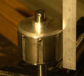
What is the best way to go as to adding sensors to a Astro motor- hall devices, or optical sensors?
The first problem that needs to be addressed is the on/off timeing lenght, the purchaced brushless motor that have hall devices imbeded in them. Is there any design in the placement? or is it just pot luck? The sensors that are in the motors are latching type to keep the noise problem from a false trigger as a on/off could induce?. They turn on/off as to a fixed crossover point as to the rotation of the magnets from north to south, with no adjustment. Maybe the margin of error is in the "noise" (not importment) as far as the timeing is concerned.
If the way this happens to turn out is the optimum placement, and best triggering on/off point, I could attach a 200count endcoder (in quadradture, sp?) to the shaft of the motor which would give about a .008 thousandths error on a 2" circle (a 1000 X 4 would be better), if the turn on/off point is not in the center of the magnets location.
Constructing a timing disk, (external) using say a .250dia. ~ magnet on a .500 center line, on a say a 2"~ or so dia., (depending on the magnet count) would give say a 50/50 turn on/off point, keeping the same number of magnets but increasing/decreasing the dia. of the magnets placement would change the pulse lenght, could this be determined by anything other than trial and error as viewed of a scope? Increased no load current by having on pulse to long? too short would not give the maxium HP output?. Would it be better than adding a one shot device and a timing capacitor? more induced signal noise?
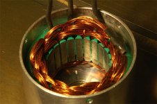
The optical disk interrupter system still requires a selection of the correct width of the open/closed vane. Using lower voltages, and amplifiers, could be more sensitive to extraneous noise, and dust/dirt.
Lets hear your input. Any experts out there on parameters of brushless motors?
Jim
The first problem that needs to be addressed is the on/off timeing lenght, the purchaced brushless motor that have hall devices imbeded in them. Is there any design in the placement? or is it just pot luck? The sensors that are in the motors are latching type to keep the noise problem from a false trigger as a on/off could induce?. They turn on/off as to a fixed crossover point as to the rotation of the magnets from north to south, with no adjustment. Maybe the margin of error is in the "noise" (not importment) as far as the timeing is concerned.
If the way this happens to turn out is the optimum placement, and best triggering on/off point, I could attach a 200count endcoder (in quadradture, sp?) to the shaft of the motor which would give about a .008 thousandths error on a 2" circle (a 1000 X 4 would be better), if the turn on/off point is not in the center of the magnets location.
Constructing a timing disk, (external) using say a .250dia. ~ magnet on a .500 center line, on a say a 2"~ or so dia., (depending on the magnet count) would give say a 50/50 turn on/off point, keeping the same number of magnets but increasing/decreasing the dia. of the magnets placement would change the pulse lenght, could this be determined by anything other than trial and error as viewed of a scope? Increased no load current by having on pulse to long? too short would not give the maxium HP output?. Would it be better than adding a one shot device and a timing capacitor? more induced signal noise?
The optical disk interrupter system still requires a selection of the correct width of the open/closed vane. Using lower voltages, and amplifiers, could be more sensitive to extraneous noise, and dust/dirt.
Lets hear your input. Any experts out there on parameters of brushless motors?
Jim
")