liveforphysics
100 TW
This video does a great job of showing why motors have laminated stators.
[youtube]TPijeVdtMIw[/youtube]
[youtube]TPijeVdtMIw[/youtube]
")
Toorbough ULL-Zeveigh said:the reason why motors have laminations is a global conspiracy by the oil companies.
Thud said:I thought Eddie was the dog on the Fraiser show......
that is an awsome magnet the guy was playing with.....I would crush a finger for sure with that hog......or it would fly through the wall on its way to mate with th lathe! I had a stack of motor magnets in my pocket & ripped my Jeans when i got latched onto the macine....candid camera moment.
liveforphysics said:This is why we like our laminations as thin as possible, and from a metal that conducts as poorly as possible (while still having good magnetic flux guiding properties). Make a stack of a bunch of insulated 0.2mm thick silicon steel laminations, and now those magnets only get a path 0.2mm thick to induct a charge into, making the potential voltage difference very low, and the silicone steel makes the resistance of the steel high to limit the current flow potential from that small voltage difference, and being insulated makes them each behave like a separate unit, so if you've got a 3" thick stator or a 1" thick stator, it only behaves as the sum of the individual lams (rather than getting a huge voltage difference shorting across a wide stator).
Jeremy Harris said:One consequence of eddy current loss (and the subsequent heating effect) caused me some angst on the first prototype boat outrunner propulsion unit I made. To protect the motor and controller from getting wet I put them inside an alloy box. Unfortunately, the box I used was a bit small, so the clearance between the outrunner bell and one inside face of the alloy box was only around 1mm (I actually had to use the Dremel to grind the inside out to stop the motor touching in places).
I didn't notice any particular problem when bench testing (with the case off), but when I ran the motor at speed on a boat the case soon started to get pretty hot, almost too hot to touch after about ten minutes or so. I couldn't understand where the losses were coming from at first, because whenever I took the case off to bench test the motor everything seemed fine. It was only when I went to slide the case on when the motor was running that I felt the drag and realised I'd been a complete plonker............
This is worth knowing about if you're fitting an outrunner close to anything metallic. There's enough rotating leakage flux coming through the outside of the can to cause potential problems if you have anything metallic within about 10mm or so of it. My present set up uses a much bigger alloy box, with the motor well clear of the case, and doesn't seem to suffer any additional losses from eddy currents, as far as I can tell.
Jeremy
amberwolf said:I wonder if this could be an effect with any consequence on hub motors in close-clearance forks? Or if it makes a difference to heating of the motors because of the cast motor centers (not the lams but what the lams/etc are affixed to)?
How would one be able to test for this kind of issue?
amberwolf said:I know some motors use laminated construction all the way to the axle, like my cieling fan motor (rewound to become a BLDC eventually, once I can get magnets for it). Would those theoretically have lower losses of this type than the hub motors that only have laminates at the windings, but solid metal inside that radius?
What we need is a camera that can see magnetic fields just like IR or light or whatever.
Jeremy Harris said:There's enough rotating leakage flux coming through the outside of the can to cause potential problems if you have anything metallic within about 10mm or so of it.
SoSauty said:Jimminie,
I've been contemplating fashioning a copper heatsink to snuggly fit around an inrunner due to its' thermal conduction character. Whoah, looks as if that could be disasterous!
Yet what about the aluminum heatsinks I've seen??
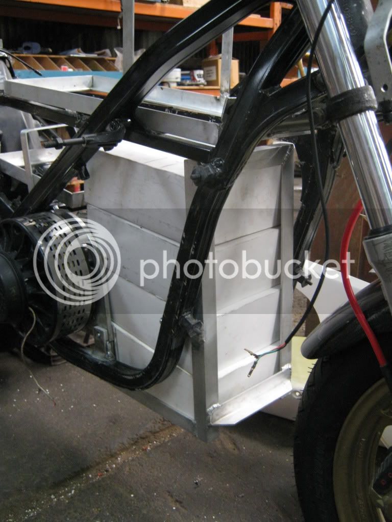
jonescg said:This is interesting... I have a lot of aluminium around my motors - the plates they are bolted to, and the frame of the bike...Hmm, next bike is going to be a carbon fibre one, with carbon fibre mounting brackets and carbon fibre bolts...