How do brushless ebike motor controllers work?

dozentrio

10 kW
Joined
May 26, 2009
Messages
516
Location
Canada
I know this is a pretty general question and, if you understand how controllers work, you're thinking "well, where to BEGIN!"

So, maybe instead of a complete lesson on electronics, maybe you can just confirm or correct what I think I know, and fill in the gaps.

The controller has to spin the motor, so to do that it has to provide varying levels current to phase wires. The power mosfets are switched on and off at the appropriate duty cycle to make that happen, and the micro controller has been programmed to know which mosfets need to be turned on, when. The hall sensors read what position the magnets are in, relative to the stator, and this (on-off) signal is read by the MCU as fast as it can manage.

Where I am a little fuzzy is how the MCU turns the appropriate mosfets on, about forward and reverse currents, and what happens when the motor freewheels (throttle zero).

I figure there are 3 (or maybe 6?) I/O... well, outputs, on the MCU which are amplified and fed to the mosfet gates. To turn the power mosfets on, a sufficient gate charge is required. And the right voltage, relative to the drain and source? The signal from the MCU is amplified by using smaller transistors, so that sufficient current gets fed to the gate. Does anyone know, btw, the part number for these smaller transistors for the infineon controllers? I think mine got 'sploded.

What are the capacitors for? The big honkin' ones and the three smaller ones (one per phase) ? What about the teeny tiny capacitors in the gate driver circuitry?
 
Tough question to answer in a simple way.

First off, the controller is doing two things:

1. It's using the Hall sensor feedback to determine the speed and position of the rotor and making sure that the outputs from the three phase drive terminals are in sync and able to continue driving the motor. This bit happens pretty much irrespective of throttle setting - if the motor is turning then this loop keeps on working.

2. It's using the throttle input to determine the duty cycle of the pulse width modulated signal applied, separately, to the output FETS. This PWM is at a much higher frequency than the highest frequency from the three phase part and works just like the PWM on a brushed controller. The PWM duty cycle determines the voltage that the motor sees, so sets the motor speed.

The MCU drives 6 lines in a stepped sequence to produce a pseudo three phase signal at the phase outputs. It runs a fixed switching sequence, with enough time delay between pulses to make sure that two FETs in the same phase are never turned on together. The result is an approximation to a normal three phase mains supply, but at a frequency determined by the motor rpm (derived from HAll feedback) and an rpm determined by the PWM duty cycle (derived from throttle setting). There is an illustration of the switching sequence in this Microchip application note that might help explain things: http://ww1.microchip.com/downloads/en/AppNotes/00885a.pdf

The big capacitors are there to smooth the big phase current pulses. Without them the supply rails would get pulled down during the high current peaks. These capacitors act to deliver enough current during the high current part of the pulse, then absorb the excess current during the next part, so keeping things reasonably smooth and avoiding large voltage transitions on the FET supply rails.

The three smaller capacitors in the gate drive circuits are bootstrap capacitors. They are there to lift the drive voltage up during the hi side FET turn on phase. What happens is that when the hi side FET is turned off, and the lo side FET is turned on, the negative terminal of these capacitors, whcih is connected to the phase output to the motor, is held low. The capacitor then charges up, through a diode, from the +12V supply in the controller. When the lo side FET turns off, the voltage is stored in the capacitor and is available to turn the hi side FET on. As the hi side FET turns on, the gate voltage needs to remain higher than the controller supply voltage, but this happens automatically due to the negative terminal of the capacitor increasing in voltage, relative to ground, with the stored charge in the capacitor continuing to supply the needed gate voltage.

Hope this makes things clearer.

Jeremy
 
Jeremy Harris said:
Tough question to answer in a simple way.

First off, the controller is doing two things:

1. It's using the Hall sensor feedback to determine the speed and position of the rotor and making sure that the outputs from the three phase drive terminals are in sync and able to continue driving the motor. This bit happens pretty much irrespective of throttle setting - if the motor is turning then this loop keeps on working.

2. It's using the throttle input to determine the duty cycle of the pulse width modulated signal applied, separately, to the output FETS. This PWM is at a much higher frequency than the highest frequency from the three phase part and works just like the PWM on a brushed controller. The PWM duty cycle determines the voltage that the motor sees, so sets the motor speed.

The MCU drives 6 lines in a stepped sequence to produce a pseudo three phase signal at the phase outputs. It runs a fixed switching sequence, with enough time delay between pulses to make sure that two FETs in the same phase are never turned on together. The result is an approximation to a normal three phase mains supply, but at a frequency determined by the motor rpm (derived from HAll feedback) and an rpm determined by the PWM duty cycle (derived from throttle setting). There is an illustration of the switching sequence in this Microchip application note that might help explain things: http://ww1.microchip.com/downloads/en/AppNotes/00885a.pdf

The big capacitors are there to smooth the big phase current pulses. Without them the supply rails would get pulled down during the high current peaks. These capacitors act to deliver enough current during the high current part of the pulse, then absorb the excess current during the next part, so keeping things reasonably smooth and avoiding large voltage transitions on the FET supply rails.

The three smaller capacitors in the gate drive circuits are bootstrap capacitors. They are there to lift the drive voltage up during the hi side FET turn on phase. What happens is that when the hi side FET is turned off, and the lo side FET is turned on, the negative terminal of these capacitors, whcih is connected to the phase output to the motor, is held low. The capacitor then charges up, through a diode, from the +12V supply in the controller. When the lo side FET turns off, the voltage is stored in the capacitor and is available to turn the hi side FET on. As the hi side FET turns on, the gate voltage needs to remain higher than the controller supply voltage, but this happens automatically due to the negative terminal of the capacitor increasing in voltage, relative to ground, with the stored charge in the capacitor continuing to supply the needed gate voltage.

Hope this makes things clearer.

Jeremy

You sound like you really know a lot. Can I ask you a question? I just burned out my rc hoobyking speed controller running a friction bike drive. Something smelled funny and I opened it up and one of the MOSFETS blew up. My question is does each phase coming out of the speed controller have 2 sets of mosfets and not just one per phase and why. I thought it uses one mosfet or a parralel group for more current on each phase.
 
Jeremy Harris said:
Tough question to answer in a simple way.

The three smaller capacitors in the gate drive circuits are bootstrap capacitors. They are there to lift the drive voltage up during the hi side FET turn on phase. What happens is that when the hi side FET is turned off, and the lo side FET is turned on, the negative terminal of these capacitors, whcih is connected to the phase output to the motor, is held low. The capacitor then charges up, through a diode, from the +12V supply in the controller. When the lo side FET turns off, the voltage is stored in the capacitor and is available to turn the hi side FET on. As the hi side FET turns on, the gate voltage needs to remain higher than the controller supply voltage, but this happens automatically due to the negative terminal of the capacitor increasing in voltage, relative to ground, with the stored charge in the capacitor continuing to supply the needed gate voltage.

Hope this makes things clearer.

Jeremy

Very nice explained. Thank you. I want to increase phase amp i my bike and test it. I have just some cheap sine wave controller without programming. Hove someone idea how i can do it?
 
Increase just phase amps? If they're not programmable, you can't.

The cheap controllers that don't measure phase currents directly have no way to change phase current other than to change (in the MCU) the ratio of battery current to phase current, because the MCU is just measuring battery current and guessing based on the ratio that's set what phase current might be. It has no way to actually know.
 
dozentrio said:
I know this is a pretty general question and, if you understand how controllers work, you're thinking "well, where to BEGIN!!
You can see our OpenSource firmware, including the schematic for the Kunteng / BMSBattery S controllers: https://github.com/OpenSource-EBike-firmware/BMSBattery_S_controllers_firmware
 
amberwolf said:
Increase just phase amps? If they're not programmable, you can't.

The cheap controllers that don't measure phase currents directly have no way to change phase current other than to change (in the MCU) the ratio of battery current to phase current, because the MCU is just measuring battery current and guessing based on the ratio that's set what phase current might be. It has no way to actually know.

So the only i can change is battery current in my controller. My controller is little bit different than others. I got it from mxus. In phase B (middle from all 3 phazes) i have got ACS758 (Hall-Effect-Based Linear Current Sensor IC with 100 μΩ Current Conductor). Maybe there is a way to connect usb to MCU. I see some pins where is no wire and could be going to microcontroller. I will need to spend lot of time checking datasheet from microcontroller. Maybe not worth it for few amps. I see they have new controllers 100A for US160 and 150A for US180. Probably the same controller. Thanks for your answer amberwolf!
 
Dariusz said:
I got it from mxus. In phase B (middle from all 3 phazes) i have got ACS758 (Hall-Effect-Based Linear Current Sensor IC with 100 μΩ Current Conductor).
Maybe you are luck because that may be KT controllers and we have our OpenSource firmware for them :)

Please see our project page and compare the images of the controller board!!
 
casainho said:
Maybe you are luck because that may be KT controllers and we have our OpenSource firmware for them :)

Please see our project page and compare the images of the controller board!!

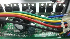
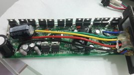
I have KT controller. On my board i see http://www.szktdz.com

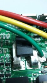
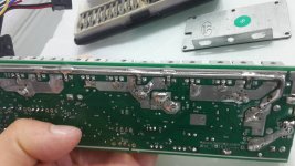
23023176_888935574604398_1517026130_o.jpg23030709_888935704604385_1887781654_o.jpg23131360_888936717937617_1395686946_o.jpg
I already made some modifications. Biff up traces pulling now 74A and waiting for new capacitors. My plan is to pull 90-100A

23030839_888935847937704_127717806_o.jpg

I will add pictures later what i have after modifications. I will look on your page :) Nice. Thanks
 
See if you can understand our OpenSource firmware, that part that we setup the motor current based on throttle value:
 
casainho said:
See if you can understand our OpenSource firmware, that part that we setup the motor current based on throttle value:
I had little programming at school. I was on IT. Your project is very helpful. Just need find where i can attach USB cables. What about changing parameters in display on C5 parameter? Didn't understand that before. I guess i have 42 on this parameter.
 
Dariusz said:
casainho said:
See if you can understand our OpenSource firmware, that part that we setup the motor current based on throttle value:
I had little programming at school. I was on IT. Your project is very helpful. Just need find where i can attach USB cables. What about changing parameters in display on C5 parameter? Didn't understand that before. I guess i have 42 on this parameter.
The firmware is experimental only for now and tested only on BMSBattery S06S (KT 250W controller). Please keep a look on the project an follow us, maybe soon we can have kind of stable firmware -- I already did 2 rides with my EBike with this firmware and next weekend I want to do another ride using the S12S controller (I think is the same as yours).
 
I saw your picture of 18 FET controler on your website. Its basicly the same as mine. I have 12 FET's little bigger capasitors and currend sensor as i said before.
 
Back
Top