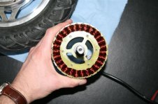
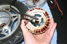
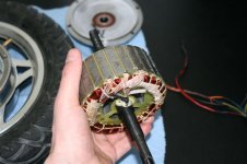
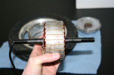
golden motor 12inch hub motor.

nieles

10 kW
Joined
Jul 14, 2008
Messages
683
Location
The Netherlands
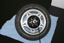
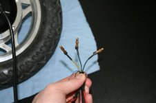
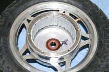
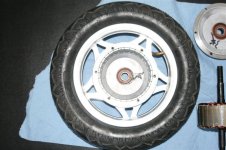
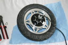
i was discussing this motor with John in CR via pm, but i thought i would share these picures with everyone, because i have not seen any photos of this hub on the forum.

some data:
Stator diameter: 104.75mm
stator thickness: 41.5mm
lamination thickness: 0.5mm
slot count: 27
Magnet count: 30
magnet wire: 5x 24awg (i think, not 100% sure)
number of turns: ?

IMG_9304 (1).jpg
IMG_9309 (1).jpg
IMG_9311 (1).jpg
IMG_9315 (1).jpg
IMG_9316 (1).jpg
IMG_9330 (1).jpg
IMG_9332 (1).jpg
IMG_9333 (1).jpg
IMG_9334 (1).jpg

Niels
 
It looks like a fine little motor for a light scooter or something.

You're a good man for taking it apart to measure it and show us the guts. Thank you.
 
liveforphysics said:
It looks like a fine little motor for a light scooter or something.
You're a good man for taking it apart to measure it and show us the guts. Thank you.

Yes, thx Nieles. Not that it matters but the magnet count must be an even number.

Luke,

You look at it and only see a 10.5lb scooter hubbie, but I look at it and see a potential self ventilating RC killer in the 5-6lb range that is simple to implement. GM's motor test report shows it to have a Kv of 12.4 . The thing concerning me is the peak efficiency of 80% at 36V. The laminations look nice and thin, so unless there's an overall design flaw or they did something like use regular steel for the lams, the motor should be capable of much better. Maybe that just not a high enough voltage. My hubbies do upper 80's in efficiency, but that's at more than double the rpms of this one at no load 36V.

First I'd cut the wheel off and get it down to the raw motor, and see how it handles a 20s batt pack with a 20A limit on the controller as an easy to install mid drive. If it seems happy at that 1500W peak, then I'd go to town:
First a rewind to triple the Kv and greatly increase the current handling and operating rpm.
Turn the housing into a centrifugal blower expecting to see 2krpm+. Assuming the rewind left a nice pathway between the coils, Thud style, I'd set the blower up different than I've done other hubbie ventilation. On this one I would almost totally block flow through the stator spokes. Instead, I would take air in near the center on one side, with exit holes only in one cover on the other side, so the cooling flow would be forced through the windings. If that didn't flow enough air due to the small diameter, then I'd mod the intake side with a larger bearing and go active with 2 or 3 server blowers.

The end result is mid drive that would fit on the chain or seat stays of most bikes just by going to a 20" wheel, with a simple reduction to the wheel. Run it at 24s and 60-70A and you're in business with nice compact and lightweight power for the average Joe.
 
spinningmagnets said:
Also, looks like theres room in the axle to boost the phase-wire size? (maybe add a temp probe?)

On my 9C I used multiple strands of 20ga magnet wire for my through axle phase wires with the whole bundle sheathed in one layer of electrical tape (to hold it in one tidy bundle and give a slight bit of protection), and then a single shrink wrap over that. I included the halls and one extra pair for a future temp sensor. It worked great for getting a nice bundle through the axle, but that was the easy part. What I failed to arrange ahead of time is a good and easy way to strip the varnish near the ends. I ended up scraping forever with a razor knife, but it was still difficult to solder, and once it was all said and done one strand of one phase didn't end up electrically connected. Since that would be nearly impossible to track down, with only 1 of 11 missing, I just cut an inch off the other end for equal resistance for all.

After it was all said and done, I think Luke's way is better. Strip the thick insulation off some wire. Put a bundle for each phase each in its own shrink. Take those 3, plus the hall wires, plus an extra pair inside another shrink and heat it to get down to a nice circular bundle to go through the axle. For a motor like this one, don't strain yourself and start with a good flexible 12ga, since this motor won't see high enough currents to warrant 10ga phases. If you want overkill, do the 10ga outside the motor, which is a longer run anyway.
 
yes, i ordered some 12ga wire for the phase wires. and will use shrinkwrap as insulation.

with a bit of luck i can install the new phase wires this weekend.

the only thing holding me back from testing then would be my controller. 60v max right now. (so 10s is an option but not very exciting.)

i have an unpopulated 6 fet controller, so i have to order some 4110 fets to do 16s and 20s tests with lipo.
 
nieles said:
yes, i ordered some 12ga wire for the phase wires. and will use shrinkwrap as insulation.

with a bit of luck i can install the new phase wires this weekend.

the only thing holding me back from testing then would be my controller. 60v max right now. (so 10s is an option but not very exciting.)

i have an unpopulated 6 fet controller, so i have to order some 4110 fets to do 16s and 20s tests with lipo.

If you're interested in the mid-drive route, another option to avoid a rewind is to get a high voltage controller from Lyen that will take up to 150V fresh off the charger. You can't change current handling or the torque constant, so the only viable option for greater power is increasing the voltage as much as economically possible and gearing down for more torque. That said, some DD hubbies are rated and given controllers for a Chinaman in Beijing, or someone in Japan, Australia, or Europe where power limits are extremely low, so they are extremely conservative to ensure durability for unforeseen heavy loads. It may turn out that this motor can handle much more than the rated 15A, and if so, then 30A at 130V nominal would be a thing of beauty for a motor this size and price, sensored, and able to run using cheap ebike controllers. It's got me thinking seriously about a multi-motor cart of some type. :mrgreen:

One thing. Were you looking at the actual magnet wires coming off the windings for the 5 small conductor for the phases? Maybe it's the small size of the motor misleading me, and it takes more turns of a small gauge than I'm thinking to get the Kv down to a useful level for a hub motor. 5 strands of 23 or 24ga is the equivalent of 16 or 17ga, which looks about right for those spindly phase wires coming out of the motor, but what the motor is wound with could be quite different and you'd have to look under the white protectors covering the phase wire solder joints to know for certain.

John
 
John in CR said:
I look at it and see a potential self ventilating RC killer in the 5-6lb range that is simple to implement. GM's motor test report shows it to have a Kv of 12.4 . The thing concerning me is the peak efficiency of 80% at 36V. The laminations look nice and thin, so unless there's an overall design flaw or they did something like use regular steel for the lams, the motor should be capable of much better. Maybe that just not a high enough voltage. My hubbies do upper 80's in efficiency, but that's at more than double the rpms of this one at no load 36V.

Since there are 30 magnets, and if the laminations are 0.5mm, I wouldn't want to push this motor much past 1200RPM.

Eddy currents go up with the square of frequency, and are related to the square of the lamination thickness. Most RC motors have 0.36 mm laminations. With this stator you will have about 2x the core loss / kg at a given freqency as a 0.36mm lamination motor. Combine that with a heavy stator and I think 300Hz operation (which is 1200 RPM) will be starting to push your luck the core loss. Maybe for short bursts you will get up to 2000 RPM, but I would test it before even thinking about that possibility. This is probably the reason for the low efficiencies. It was designed to be cheap, and operate at relatively low RPM.

-ryan
 
Nieles,

It looks like we need another favor. That is to see how thick the sheets of metal are making up the iron of the stator. My eyes aren't that great, so the easiest for me is to mark off 1cm and count how many. We're hoping for more than 20.
 
check the First post
lamination thickness: 0.5mm
i counted 83 sheets.. (for the total stator minus insulation sheets, 41.5mm)

when i am home in 2-3 hours, i will make sure its really 83
 
nieles said:
check the First post
lamination thickness: 0.5mm
i counted 83 sheets.. (for the total stator minus insulation sheets, 41.5mm)

when i am home in 2-3 hours, i will make sure its really 83

Sorry. I was sleeping on the job. 1200rpm under load isn't bad, though it throws the rewind need out the window. Ventilated for better current handling seems about the best thing to do. If it seems promising at the highest voltage controller you have, one of Lyen's HV controllers and a 30s pack may be just the ticket. 1000rpm leaving the wheel on would be 35mph, which seems possible if it will take 30A.
 
i have an unpopulated lyen 6-fet controller. i need to find some 4110 fets for it.

i also have the pcb's to make the "simple bldc controller" by jeremy harris.
but i dont have the parts to build the controller yet (only have the brain mc33033 chip)

i think the 6-fet controller is perfect for this motor. the simple bldc controller would be overkill IMO (with 4468 100v fets)

i think i am going for 24s max. i dont feel very safe with voltages above 100v dc.
 
Back
Top