Agni motor tuning and racing

Jozzer

100 kW
Joined
Apr 19, 2007
Messages
1,069
Location
Swindon UK
THIS FORUM IS NOT SAFE. DO NOT CLICK ON ANY ADS ON THESE PAGES! (In case they delete sigs)

Hi guys,

This thread is a long time overdue so I'll start it rolling now! I've not got a huge amount of time on my hands, but will try to do it in stages. hopefully Cedric Lynch himself amoungst all the others with experience will chip in..

First tip...

READ THE WORKSHOP MANUAL!
Cedric wrote it himself, think of it as "The Agni Bible" :lol:
I'm constatly surprised how many people who call for help have NOT read it.
http://www.agnimotors.com/workshop_manual_v1.pdf

Next up, I'm sure you all want the nitty gritty bits, not lectures on how important ventilation is to an air cooled motor, so on to ...

TIMING.

If your running your motor on very light loads and using regen too, then neutral timing is fine. However if you need to push a lot of power then brush advance is required. To run on maximum loads, extreme advance is required.
Agni motors have the neutral position marked on them, but even so it's good practice to verify this when you first recieve the motor, or when changing to a new brushholder. You all know how to do this already, because you read about in the workshop manual!! :wink:
Once you know where neutral is, you can advance the brushholder by turning it INTO the direction of travel (IE, if motor is turning clockwise, you turn the holder ANTIclockwise).
I would suggest 1MM advance for every 150A or so from personal experience, though Cedric will hopefully give a more accurate figure based on his many years dyno testing of his work in motion.
The timing process plays an important part in motor balancing that I'll cover later.
 
I'm realising I should have taken the time to organise notes before trying to write it all out in one go....but I'll stumble on, perhaps someone will tidy up later for me!

So, since something that I started off is actually causing one of the causes of motor abuse, lets talk about paralleling motors. Since we are pushing the motors to 100% electrically and thermally, if there is any inbalance between the resistances of each motor setup it would mean that one motor is then running at greater than 100% of its capability. It won't do that for long..
If you want a pair of PM motors to share load equally, you must;
1. Ensure that all cabling between motors and controllers are of equal length, and all connectors well crimped and bolts fastened.

2. Use motors that spin at the same RPM for every volt applies (I'll call these "Matched Motors"). To verify the RPM/V of the motor, simply connect a low voltage power source (around 10-20v is fine) with the brushholder set in the neutral position, and measure the RPM of the shaft and the voltage present at the motors terminals. Divide the RPM by the voltage read and you have your figure. You should find 71RPM/V, but due to some manufacturing inconsistencies out of Agni's control, there was actually a spread of 62-74RPM/V for one batch last year, which of course is terrible on a parallel motor setup. Match to within 1 RPM/V if possible, 2 RPM/V absolute worst (anymore and I'd not run them together, or limit speed until a better match was found).

3. Take extra care that the brushes are of equal resistance (all positive matched, and all negative matched). To test brush resistance, set up a power supply for around 10A 10V (doesn't have to be precise, as long as you can repeat the test accuratly at the same power). Attach the PSU leads to each end of the brush (croc clips), current will flow. Place multimeter probes at eather end of the brush also (but touching the carbon, not the croc clips) and measure the voltage. You should see something in the region of 20-100 millivolts. Sort them into batches as close as you can manage to matched, and use lowest resistance brushes on the positive terminals, the next lowest batch on the negative terminals. Again, hopefully the variance of brush resistance is a temporary affair (until the brush manufacturers get their act together!!) and the high quality that I remember from yesteryear will return!

4. Match and balance the timing at the correct level of advance so that the motors share load equally. To accomplish this accuratly you need to be able to load your vehicle (ie, with a dyno) and measure current to both motors with the throttle fixed in position at a set power level. It is possible, for instance, to balance at lower current on a motorcycle by simply using a paddock stand and holding the rear wheel at 30mph or so, but since you are working at less than 50A current, any differences will be amplified when you later apply 600A+ to the pair. I'd want to see at least 100A per motor and within 5A of each other before calling a pair balanced. Hitting the rear brake can buy you a few seconds at higher current, but the brake will overheat real fast, and you may need to take your time over the process. Uni-T clamp meters ($30) are fine for the job, does help to have 2 so you can leave them setup and glance from one to the other, but it is possible with one to swap from side to side.
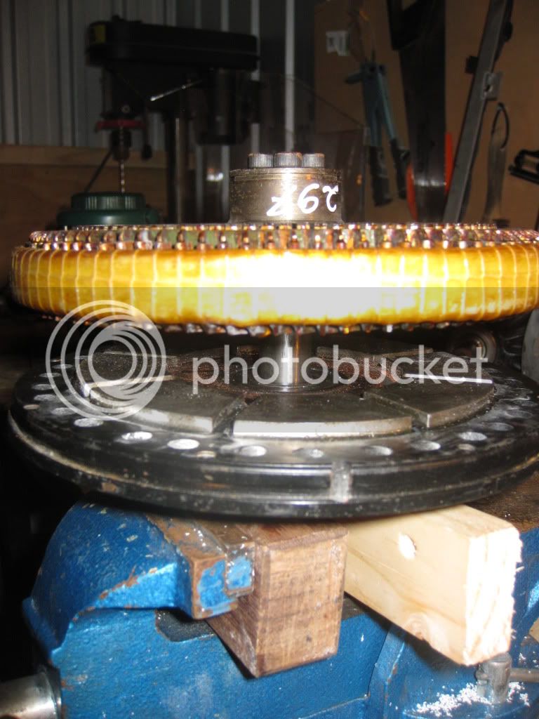
Brush Fettling.

It can help improve commutation (reduce sparking) if the brushes are fettled slightly. Since the centre of the commutator angles slightly inwards, effectivly timing in this small area is different to the timing over the rest of the brush surface. Removing the inner corner of the brush helps aleviate heat buildup in this area.
100_1736.jpg
View attachment 1.
Of course, ensure at all times that the brushes can move freely and the spring pressure feels even before assembling.

The brush holders are made of Bakelite, one of the properties of this material is that when it cures it changes size slightly, leading to a small variance of holder size. If you find that a replacement brush holder is a slopooy fit in the motor, wrapping a layer of insulation tape to help keep it centred in the motor can make balancing that much easier..


Motor Speed.
The reinfoced Agni 95R can spin at a maximum speed of 6000 RPM saftely. Exceeding this limit can cause the copper to fly apart, especially if it has also been overheated to the point that the solder holding the connecting strips is loosened at the same time.This usually corresponds to around 80v, though as mentioned above, if your motors RPM/V is different to standard you may need to recalculate.
If a battery voltage of higher than 80v is used, some provision must be made to limit speed/voltage supplied to the motor. Kelly controllers for instance can limit top motor speed/voltage with a setting in the software, a stand alone system to cut throttle if the speed/voltage limit isn't too hard to work out. (Here are some words of wisdom from Cedric on the matter, copied from a recent reply to a customer.." You could arrange an absolute limit by connecting a 500ohm resistor in the wire between the throttle potentiometer wiper or Hall-effect output and the controller throttle input and connecting the output terminals of an opto-isolator between throttle input and ground on the controller; now if you connect the input of the opto-isolator to the controller output or one of the motors via a Zener diode of about 80V and a resistor of a few hundred ohms, when the motor voltage reaches about 85V the opto-isolator will start to conduct and will override the throttle to limit speed.")

As far as motor current goes, the motor can take instantaneous loads of 500A, a few seconds at 400A, and 230A continuous (more with adequate ventilation). Bear in mind however, that if you trying to run a race, and hit the motors with 500A several times in a lap, you may well push past the thermal limitations of brushes and motor faster than you'd expect. For this reason, I would reccomend a controller with 400A peak output, especially if using a controller that can actually supply it's peak rated current for more than a few seconds (ie, the older Kelly casings, KDHA/B, supply full current perhaps once in a race, the newer KDHE type housings can supplypeak power every time you open the throttle fully when properly cooled). A KDHE 800A would be a good racing controller for a pair of motors (Although I am known to use 1200A controllers, they are limited for the track to 65% power. For a drag race you might get away with a stting of 80% without damaging motors, 100% with a fair chance of cooking a few brushes, but if you do this on a proper track race the bike will not finish the distance!!)

High Current at High Speed.
Now, although an Agni can take high currents for short periods at reasonable RPM's, things change at higher speeds. you might think of it as the motor having a power/KW limit as well as individual voltage and current limits. Basically, short bursts of even 500A and above will not result in brushes arcing at less than 4Krpm, but as speed increases arcing becomes more and more of a problem, and at above 5Krpm even 330A can cause quite a firework display. It is possible with the newer KDHE Kelly's to set a battery current limit as well as motor current, which seems to work fairly well, and has the effect of cutting back current only at higher RPM.
Most of you already know about how controllers effectivly multiply current at lower speeds on an Ebike controller, well, most larger controllers actually limit motor current rather than battery current, so the effects are slightly different thought he principle is the same. Basically, at low speed when you fully open throttle the motor will be supplied with the full set current, and this will continue until motor voltage comes close to battery voltage at which point current can no longer flow freely and starts to drop.
With the new controller modifications (thanks Fany), it is possble to set motor current at say 100% (assuming perhaps a 500A controller on a 84v pack), and set battery current to 300A, then you have effectivly given a power (KW) limit that will stop high current being applied once speed increases to a certain point.
Of course, it would be possible to come up with other means of controlling high speed power, simplest being to reduce throttle when going fast;)


More soon,

Steve
 
I'm pumped Jozz!

It will be great have Cedric post here. He is such an awesome guy.
 
Awesome somebody read my mind! LOL..
 
Definitely Interested. It's about time I built a big bike. I've got my eye on the Agni. Anyone have any recommendations on where to get them?
 
If it's OK with Cedric can you post some good pictures of what is inside the Agni when disassembled?
 
I tipped Cedric off about the thread. He's very busy, but if I make enough cockup's he'll showup to put me right;)

Ahh BigMoose, see, someone hasn't been reading his manual already, there a good few pics in there :wink: I will however get some more shots together for later on in the thread.

I'll be back tomorrow with some more..


Steve
 
Steve, I have looked at the manual and pondered it. The photos are a little dim, and I find it a bit hard to see detail. The pictures are very good to make the assembly/disassembly point that Cedric is making however. What I was hoping for was trying to see the layout of the laminations, coils and commutator. The architecture of the magnetic path. I have never owned an Agni nor had the pleasure of taking one apart. Perhaps I should look for the patents. I want to try to understand the beauty of the design!

Found two pretty good patents that show the internals from a few years back. I was surprised to see the cantilevered bearing!

PS: Thanks Chris! Your thread below is exactly what I was looking for! Great pix of the internals and how they all go together. Wonderfully efficient design Cedric invented, both electrically efficient, and piece part efficient.
 
I have an Agni Motor Maintenance thread here: But it is mostly about how to change a bent or damaged motor shaft. I also have lots of pictures of the inner goodness of an Agni motor :D
http://www.endless-sphere.com/forums/viewtopic.php?f=30&t=27795

Keep up the good stuff Jozz!
 
This is a correction to my previous post, which was totally wrong about this brush-holder I didn't know anything about.


I was totally wrong about this brush-holder, its materials, and its function. A friend had found it in a box at work, and didn’t have any idea what it was or who made it. I gave it a 5 minute look, and very incorrectly assessed materials and badly mis-judged its performance.

The brush-holder slot itself is actually an aluminum piece, not plastic like I had thought it was (appeared to be a cut-up stock Agni plastic brush holder to me). The piece that appeared to be just an aluminum rod is actually a heat-pipe setup for the proper temp range of the brush operation, which makes for an extremely good thermal path to the top copper plates. The top copper plates have excellent cross-section to provide a low delta-T to the outside plate fins, which are clamped with aluminum washers (not zinc plated steel). This provides an extremely good thermal path from the brush to the outside world, perhaps as good of a thermal path as has ever been done for a brushed motor.
The new designs also feature the ability to mount the heat pipe on the side of your direction of rotation, and feature a clever spring down inside the brush-holder slot to provide gentle pressure against the wall of the holder with the heat-pipe. This also prevent brushes from bouncing and chattering against the face of the commutator, which minimizes the arcing that creates tons of waste heat in both the rotor and the brush, and is frequently the cause of infant mortality in the Agni motors, or in racing situations. This is a very good thing for an Agni motor, and the motor even sounds more quiet just from minimizing the arcing and brush flutter.

The new style has also become more compact with a more optimized and easier to package fin stack-up arrangement in the later versions.

I’ve met the great guy who makes these holders, and tested them myself, and seen the impressive cooling performance and minimized brush arcing it can provide for an Agni motor.

This part would be a wise investment for folks pushing the limits of the Agni motors and experiencing melt-downs. First time it saves a motor, it paid for itself, and can prevent some of the dreaded Agni brush-holder related DNF's that we are seeing commonly at TTXGP events around the world.

I wish I had known more about it before making assumptions about it, because it really works well. The fins get hot enough to sear my finger-tip onto them, which means it's removing a ton of heat from the brushes and putting it into the passing air where it can be dissipated.

agni1.jpg


agni2.jpg


agni3.jpg


agni4.jpg
 
It looks beautiful Luke, but what is it cooling fins for the brush holder? Transferring heat through zinc plated steel washers?

On another note is the yellow/tan band in the photo below a kevlar compression band to keep the rotor together at speed?

PS:Thanks for your rebuild thread Chris, just what I was looking for.

IMG_2639.jpg


It would be great if Cedric stopped by. Sure would be interesting to hear his story of inventing this motor. Was he an experimentalist, or did he approach it analytically and in an iterative fashion? Did he "just see" the solution in his mind's eye? Wouldn't it be great to see pictures of that first motor, said to be made from "soup cans..." How many false starts did he have? What kept him going?
 
*Edited to correct content*


Nope, not Zinc plated steel washers, but aluminum washers that promote good thermal transfer into the fin stack-up. It really works to get the heat out of the brush area, and give it a place to go rather than building up in the brush-holder. It's a clever design.


You can find them here:

http://www.picoamps.de/automotive/de/products_tuning_de.htm#tk2

It is a working, and simple to implement solution to many of the failures we've seen with various TTXGP bikes at events all around the world.
 
bigmoose said:
Wouldn't it be great to see pictures of that first motor, said to be made from "soup cans..."
Did you see this one, Dave?

file.php


Ref:
http://www.bbc.co.uk/programmes/p00cqdtb
http://www.bbc.co.uk/bbcone/wallaceandgromit/hands-on/cedric-lynch-electric-motor/
 
Interesting brushholder modification. That looks like an LMC made holder, I've seen a similar heatsink arrangement (though not identical) on Quantya bikes.
 
grindz145 said:
Definitely Interested. It's about time I built a big bike. I've got my eye on the Agni. Anyone have any recommendations on where to get them?

Hi Grindz, if you can't find anyone in the US with stock, I can supply them from my shop (link in sig). In the future I will be offering motors ready fettled, and matched in pairs as a service to racers and in an effort to cut down on the amount of motor damage occuring at the track. New stock is currently hard to get (I blame Chris for killing them all;)), but should be avaialable shortly.
I do have a trickle of second hand and reconditioned motors coming through slowly..

Steve
 
Jozzer said:
(I blame Chris for killing them all ;))
Steve


That's a half truth! ;) I might have two reconditioned motors in about 6 months time too, but I don't know how they'll go paired up. Probably OK as a single-motored bike anyway.
 
Only joking Chris, Cedric will forgive you. *Hands Cedric a tissue to dry his tears*


Jozz
 
jonescg said:
Jozzer said:
(I blame Chris for killing them all ;))
Steve


That's a half truth! ;) I might have two reconditioned motors in about 6 months time too, but I don't know how they'll go paired up. Probably OK as a single-motored bike anyway.


Awesome Jozzer and Chris. I'm probably going to go single motor, since I'm it's going to be a big-enduro/adventure tourer type of bike, don't need crazy power, just lots of torque. I also want to save the space for more cells / possibly a hybrid drivetrain (not to derail the thread)
Definately let me know if something reconditioned comes up, if not Ill head your way Jozz, when the time is right. Just bought a 5304 and an 8x8 9C for a 2WD experiment first though...ahh the distractions...
 
Based on your comments in the first mail, am I correct in thinking you want to run 2 motors in
parallel but use only one controller ? Have you considered (electrically) separating the motors
by using two controllers ? The the (small) difference in rpm/V wouldn't really matter. Even nicer
would be to run using 2 constant current based controllers so that the motors would deliver (close
to) the same amount of torque
 
Lebowski said:
Based on your comments in the first mail, am I correct in thinking you want to run 2 motors in
parallel but use only one controller ? Have you considered (electrically) separating the motors
by using two controllers ? The the (small) difference in rpm/V wouldn't really matter. Even nicer
would be to run using 2 constant current based controllers so that the motors would deliver (close
to) the same amount of torque

Yes, parallel would be 2 motors on a single controller.
The problems with 2 controllers are, they must be 100% torque control, and throttle curves must match, or else motors will not load share for different reasons. Kelly's don't quite have true torque control (speed does vary at different throttle positions), and throttle response at different throttle levels is a bit hit and miss also (of the 20 odd KDHE's I used last year, they all responded differently, some giving full power early on, others requiring WOT before giving full output).
FYI, one of the teams at the track last year repeatadly burnt one motor very badly using 2 controllers, caused we believe by an RPM difference. Can't quite remember if they were using Kelly's or Brusa's (which ARE torque based), Cedric will remind me later.
Cedric's original TT winning bike uses 2 Kelly controllers and has proven itself to be one of the most reliable Agni based builds onthe track, however this might be because the bike only runs 72v, and uses the old Kelly's that can't consistantly output their rated power.
 
Ok I get your argument regarding that the speeds (or to put it better: the pwm dutycycle) of the two controllers must match...

How about splitting the output MOS transistors down the middle ? Example: lets say your controller has
6 MOS transistors in parallel capable of supplying enough current for your two motors. You split your
battery pack in two, run 1 battery on 1 set of 3 MOS transistors to supply 1 motor. The other battery
runs on the other 3 transistors and supplies the 2nd motor. Both sets of MOS transistors run on the same
switching signal.

This has an added advantage: lets say one motor draws more current / provides more torque than the other (has a higher rpm/V).
This motor will deplete its private battery quicker than the other motor. As this packs voltage goes down the current / torque
of this motor will drop while the current/torque of the other motor will rise (it has a fresher battery, remember).

So what you kind of want is a single controller running two separate power stages, each power stage with its
own battery and its own motor. This will require some tinkering, maybe some opto couplers will be involved but is not difficult....
 
Jozzer said:
Of course, it would be possible to come up with other means of controlling high speed power, simplest being to reduce throttle when going fast;)

Impossible. When you have your race face on, the only thing you are interested in is the next apex! This is where commuters and race bikes have to be built differently. Ask any racer "did your oil lamp come on during the race?" You will no doubt get an indifferent shrug :) I think as many automatic failsafes need to be built into a race bike cause the last thing on your mind is the diagnostics of the bike.

Remember how were used to say Kelly always overstated their controller capabilities? Well I don't think we can say that for the KDHE series any more :)
 
Check with Kelly to find out if your controller has the battery current limit capabilities, if not, send it back again and ask them to upgrade it. They added the function to this model some time recently, but they will probably need to check the serial number to tell you for sure.

I'm working on a little gizmo to look after and display motor temps, individual motor amps, data logging, and appropriate power limiting, sounds like you need to be a beta tester of this too;)

And indeed, Kelly made a huge step forward with the thermal management of the last generation of controllers. They really can dish out the current, and do it for as long as you can keep the controller case cool (which isn't proving too difficult at twin agni power).

Steve
 
jonescg said:
Impossible. When you have your race face on, the only thing you are interested in is the next apex! This is where commuters and race bikes have to be built differently. Ask any racer "did your oil lamp come on during the race?" You will no doubt get an indifferent shrug :)

Totally agree. Even huge bright red warning lights can't be seen in my drag car while racing (because you're way too busy trying to grab the next gear and keep it in the lane), only the shift light can be seen and it's because it's got a optical lens on the front that projects the 55w bulb's light right into your eyes.


jonescg said:
I think as many automatic failsafes need to be built into a race bike cause the last thing on your mind is the diagnostics of the bike.

This is where I would disagree. You could have things dial back current or whatever as temps exceed setpoints, but the last thing you want in a race bike is something that can shut it down at any point for any reason. You want to be able destroy the battery, motor, controller or whatever it takes to get that extra few seconds of propulsion needed if that's what it means to DNF or finish.
 
Yeah, I gotta say almost all of our riders from last year said the same (we did have overheat protection for instance, but they wanted it turned off).
I can already hear Chris complaining "but I was going to win" instead of "thank god it saved my motor" :lol:

I believe the TTXGP safety regulations insist on an LVC failsafe, so destroying batteries should not be an option. 9 out of 10 riders are scared of KFN (Nuggets)..
 
Back
Top