Lebowski
10 MW
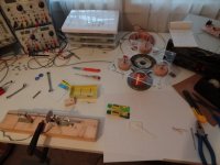
Since I was pulling apart my motor anyway I thought I'd make some pictures to show how it's built.
The motor is meant to power a bicycle. Here in Switzerland the limit for electric bikes is 250 W, above
that it doesn't count as a bicycle anymore and it gets messy in the legal department (you need a
licence plate, insurance etc etc). The motor will be mounted on the bikes luggage carrier (so above the
rear wheel) with a chain running down to the left side of the wheel. In the wheel I plan to attach a
sprocket to the spokes.
This is the assembled motor:
The motor consists of two 'magnet plates' sandwiching a 'coil plate':
The coils are embedded (using expoy glue) in a tough 5mm thick acryllic glass plate:
The magnets plates are rotating on a standard Shimano Deore rear axle. This is an easy way, if you don't have a lathe
and top mechanical building skills, to build an axle for a motor as it provides the bearings for the motor to run on, it
has a freewheel and the standard splines so its easy to attach a (low-tooth) sprocket for chain-drive:
Here you can clearly see that the rotor is attached to the axle with 3mm screws through the spoke holes:View attachment 2
With the top magnet plate removed:View attachment 1
With the coil plate removed:
This last picture shows the 25mm diameter magnets stuck to a 5mm thick iron backplate. The iron backplate is actually
a bunch of wedge shaped pieces cut (with a hacksaw, lots of blood sweat and tears) from a bar. The wegde pieces are
attached with screws to the aluminium holder.
The engine was built using simple tools, a drill press, a jigsaw and a hacksaw. When mounted to the bike it will need around
60V for 25 km/h. Coil resistance per phase is 0.65 Ohm, inductance 300 uH. It has 14 magnet pairs over 12 coils, coils
are Y-connected. The plastic coil plate is the most difficult bit to make, I had to make a small winding rig and clamping the
coils soaked in glue was messy. The plastic looks feeble but is actually very tough and can stand temperatures up to
190 degrees Celcius (way past the de-magnitising temperature of the magnets). The attachement of the coils to the plastic
is also very solid, the glue is rated at 1200N per cm^2, each coil is attached over 6 cm^2.I tried pressing out a coil on a test
pieces but (using just my thumbs) it's impossible. Test runs upto 1000rpm showed no explosive deconstruction type of behavior.
Power required to spin at 800 rpm: 11 Watts (60V 0.18A).
At the moment I finished my (also homemade) sensorless motor controller. I'm now busy with the actual power controller, for this
I need to mount the motor on my bike and then onto my Tacx home trainer. Then I start pushing power through it to see whether
my constant-current based power controller is any good