
august23
10 W
- Joined
- Feb 15, 2012
- Messages
- 79
I will edit and add stuff as I go, but for now, here are the photos to go with the thread.
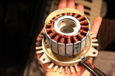
I was able to get the stator off of the rest of the motor. I did this by, assuming you already have the shaft/cup off, put a half dollar sized washer in the top where the inside most baring goes, acting as a little platform. then I used a 3/4" socket and placed it right on the washer (or whatever works to extend it up). then, while holding the stator firmly in one hand, hit the socket with a hammer as hard as you can (with the other hand). keep doing this. the impact will start to pull the stator up and off, along with the attached wires. once it's up, say a quarter inch, you can clip ALL the wires at the potting side of the wires (giving yourself some length to play with). Once you have them all clipped. you can continue to hammer away until the stator comes off. I bought some red locktite for when I put it back together. Once you are to this point, you can use a heavy duty screw driver and a hammer to chisel away at the potting. the first one I bypassed, I drilled holes all over the potting first (with the biggest bit I had). then I chiseled away. I haven't ever totally cleaned one out. infact, the last 2 I did I left the potting intact except near the exit hole where it tends to get a little tight.
here is a video of me taking off the stator: http://www.youtube.com/watch?v=xU6tsiEftCU
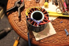
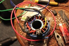
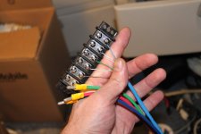
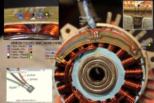
Once you have the stator off, you can easily get at the wires. you have to pair up the duplicate phase colors (yellow to yellow, red to red, and blue to blue).
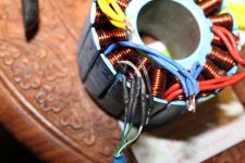
working with the stator upside down makes it very easy. to put it back together I put it back together by hand as much as I could, then put it upside down (so that the stator is on the carpet) on the basement floor with a piece of carpet. I used a piece of scrap wood between the hammer and the aluminum when I pounded it back down. I did this in several stages, picking it up and examining the 'fit' and making any final wire positioning adjustments before finally having it all back in place. I was also quite premeditated about the wire placements before I prepped the stator phase wires for extension.... which really made this step smooth and easy. keep in mind that putting the stator back on is probably the most likely step to introduce a short of some sort.... but not as likely to mess it up as when trying to do it with the stator still on the base.
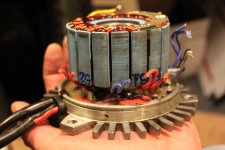
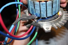
I should note that I have bypassed a few 300/400w macs too. But they can be a bit trickier. the hall sensors and sensor circuit board is on the bottom of the stator, next to the controller. and on about half of the ones I opened (5 of 10) had the board in the potting.... and the hall wires are nearly impossible to reuse. I was able to get several of them repaired by putting new wires directly on to the board contacts/original solder points. though this takes some expert solder experience. and the stator HAS to be off the base to get at the board. I used a sharp flat head screw driver and a hammer to crack the potting near the board so that when I went to detach the stator, the board would come with it freely. The power I get from these little 400w motors after being bypassed is quite noticeable and with a 15t sprocket/free wheel or more, it goes about 19-20mph on my scooter at 36v.
Relevant links/threads:
http://endless-sphere.com/forums/viewtopic.php?f=16&t=11772 (basically the same as this thread)
http://endless-sphere.com/forums/viewtopic.php?f=31&t=17683 (Lynn's controller works AWESOME for this and he is very helpful too)
I was able to get the stator off of the rest of the motor. I did this by, assuming you already have the shaft/cup off, put a half dollar sized washer in the top where the inside most baring goes, acting as a little platform. then I used a 3/4" socket and placed it right on the washer (or whatever works to extend it up). then, while holding the stator firmly in one hand, hit the socket with a hammer as hard as you can (with the other hand). keep doing this. the impact will start to pull the stator up and off, along with the attached wires. once it's up, say a quarter inch, you can clip ALL the wires at the potting side of the wires (giving yourself some length to play with). Once you have them all clipped. you can continue to hammer away until the stator comes off. I bought some red locktite for when I put it back together. Once you are to this point, you can use a heavy duty screw driver and a hammer to chisel away at the potting. the first one I bypassed, I drilled holes all over the potting first (with the biggest bit I had). then I chiseled away. I haven't ever totally cleaned one out. infact, the last 2 I did I left the potting intact except near the exit hole where it tends to get a little tight.
here is a video of me taking off the stator: http://www.youtube.com/watch?v=xU6tsiEftCU
Once you have the stator off, you can easily get at the wires. you have to pair up the duplicate phase colors (yellow to yellow, red to red, and blue to blue).
working with the stator upside down makes it very easy. to put it back together I put it back together by hand as much as I could, then put it upside down (so that the stator is on the carpet) on the basement floor with a piece of carpet. I used a piece of scrap wood between the hammer and the aluminum when I pounded it back down. I did this in several stages, picking it up and examining the 'fit' and making any final wire positioning adjustments before finally having it all back in place. I was also quite premeditated about the wire placements before I prepped the stator phase wires for extension.... which really made this step smooth and easy. keep in mind that putting the stator back on is probably the most likely step to introduce a short of some sort.... but not as likely to mess it up as when trying to do it with the stator still on the base.
I should note that I have bypassed a few 300/400w macs too. But they can be a bit trickier. the hall sensors and sensor circuit board is on the bottom of the stator, next to the controller. and on about half of the ones I opened (5 of 10) had the board in the potting.... and the hall wires are nearly impossible to reuse. I was able to get several of them repaired by putting new wires directly on to the board contacts/original solder points. though this takes some expert solder experience. and the stator HAS to be off the base to get at the board. I used a sharp flat head screw driver and a hammer to crack the potting near the board so that when I went to detach the stator, the board would come with it freely. The power I get from these little 400w motors after being bypassed is quite noticeable and with a 15t sprocket/free wheel or more, it goes about 19-20mph on my scooter at 36v.
Relevant links/threads:
http://endless-sphere.com/forums/viewtopic.php?f=16&t=11772 (basically the same as this thread)
http://endless-sphere.com/forums/viewtopic.php?f=31&t=17683 (Lynn's controller works AWESOME for this and he is very helpful too)
Attachments
-
 IMG_9475.jpg132.5 KB · Views: 1,711
 -
 IMG_9476.jpg134.2 KB · Views: 1,711
 -
 IMG_9484.jpg188.5 KB · Views: 4,497
 -
 IMG_9487.jpg151.9 KB · Views: 4,497
 -
 IMG_9492.jpg193.2 KB · Views: 4,497
 -
 IMG_9497.jpg149.5 KB · Views: 4,497
 -
 IMG_9501.jpg107.6 KB · Views: 1,711
 -
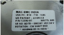 600w mac-bmc.jpg35.8 KB · Views: 4,493
 -
 IMG_9504a.jpg171.6 KB · Views: 1,711


