ian.mich said:
This has me stumped. then again, im no EE
Me neither, but I'm trying to do something similar to you, I'm trying to change the HVC on an eZee controller, as it's made for 36v and I'm using a 48v battery.
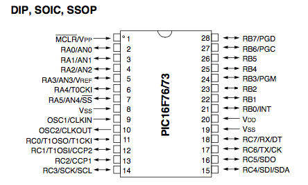
Here's what I've done so far, I think I'm almost there: First I found the main microcontroller chip, it's a PIC16F73 in my case.
Then lookup the datasheet and find the pinout, here's mine:
Pins 2,3,4 and 5 are of interest here, they are analogue ins.
What I did next was to vary my battery voltage in even steps, and measure the voltage on these pins. If you are lucky, 1 pin will vary evenly with input voltage. Here are my readings, and pin2 on the PIC16F73 was my pin that changed in proportion to battery voltage:
Battery voltage / Pin 2:
40.4v (10s) / 3.657v
32.36v (8s) / 2.923v
24.31v (6s) / 2.196v
16.23v (4s) / 1.468v
8.07v (2s) / 0.731v
Now I already know that the LVC on my controller is 28v and the HVC is 44v, and this equates to the voltage on pin2 being above 2.5v and below 4v.
What I'm doing now is trying to trace back the resistors which are in series with pin2, and I'm going to try and change the resistance so that an input battery voltage of 36v produces 2.5v on pin2 for the LVC and a battery voltage of 53v produces a voltage of pin2.
This should work in theory, but I've never done it before, so don't take my word as gospel.
Try and find the analogue in first and take it from there, let me know how you get on as this isn't easy for me either.
PS:
Resistance reduces in parallel, and increases in series.
EG 2 x 1000ohm resistors in parallel give a overall resistance of 500Ohms, but if you put them in series you'll get 2000 Ohms. Good luck.
")