Worlds Worst Dyno - Version 2

adrian_sm

1 MW
Joined
Feb 22, 2009
Messages
2,429
Location
Melbourne, Australia
World's Worst Dyno v1 has been upgraded. To include:
- torque measurement
- RPM measurement
- variable load, via regen

Basic setup.
- drive motor is fixed to an angle bracket
- driven/load motor is floating on the pillow block bearing on its axle, coupled axially to the drive motor, and the rotation it taken by a torque arm
- the torque arm is simply bolted to the stator, 200mm long, and rests on the kitchen scales via a blob of blue tack to meaure the force
- RPM readings are via the flux leaking out of a motor, a hall sensor stolen from a cheap throttle, and a cheap oscilloscope
- cycle analyst and watt meter are used to measure the input power, and regen power
- IR thermometer can monitor temperatures.

Purpose of Worlds Worst Dyno v2
- Understand more about the continuous power/torque/thermal limits of small RC motors.

fr_1707_size640.jpg
fr_1708_size640.jpg
fr_1709_size640.jpg
fr_1710_size640.jpg
fr_1711_size640.jpg
fr_1712_size640.jpg

The parts list is:
- mounting board
- three steel angle brackets
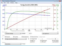
- Drive Motor: Turnigy Aerodrive SK3 - 6364-190kv Brushless Outrunner Motor
- Load Motor: C8085-250kv
- Drive ESC: Turnigy Brushless ESC 85A w/ 5A SBEC
- Regen Controller: 6fet sensorless EB306/XieChang/Keywin/eCrazyman controller (using IRFB3006 fets)
- 2x 12mm KFL001 FL001 Pillow Block Bearing Flange Block Bearing
- BF 8mm X 12mm CNC Flexible Plum Coupling Shaft Coupler D25L30
- servo tester (ESC throttle)
- 5k pot, and switch for regen controller throttle and to enable regen.
- IR Thermometer
- hall sensor from a $2 throttle and oscilloscope to measure motor RPM
- Cycle Analyst for regen controller volts and watts
- Turnigy Watt Meter for drive motor watts measurment
- kitchen scales to measure the torque load
- blue tack to keep torque arm in contact with kitchen scales, and dampen load
- 24v 600w Meanwell Powersupply
- miscelaneous wires and screws

Future Upgrades:
- lightbulb load bank for greater variety in torque loads
- datalogging RPM, torque, volts, amps in, regen power

Results so far:
- the SK3 6364-190kv was approx. 88% efficient for a 1.38Nm load @ 3850 rpm.
 
Great stuff, Adrian :D
adrian_sm said:
Results so far:
- the SK3 6364-190kv was approx. 88% efficient for a 1.38Nm load @ 3850 rpm.
That seems quite impressive. It would be interesting to compare your empirical data with the result of crunching the numbers in DriveCalc...
 
Hi Adrian,

I'll second Miles comment: Great setup.

I'd be curious about the efficiency of the regen part of it, and how it varies with rpm and regen current. I don't think real world regen efficiency has been tested/posted for these types of controllers and motors. Probably motor/controller run in brake regen is a bit less efficient than when run regularly.

It might also be possible to use the kitchen scale once to make a table of regen efficiency. Then just use this table to convert watts read on the Cycle Analyst to shaft power.

An automated solution would connect the CA serial out to a PC computer and use the computer to calculate and display shaft watts. The CA streams all measured data once per second on the serial port.

The CA has an input terminal meant to count rpm. I think it might work up to 10kHz or so, but I'm not sure exactly. In the CA-DP it connects to the hall signal on the controller. Maybe there is some what to clean the motor phase signal to feed to the CA. Or find the appropriate signal on the EB306.

Martin
 
I wish I new the formulas behind the scenes in DriveCalc, as I would love to be able to rely on it. But it is significantly different than the measured data.
Efficiency number are much lower in Drive Calc, than what I calculate based on the reaction torque and motor speed.
It also derives the motor Rd value based on the Volts/RPM/Amps measured data, even though I have measured the phase resistance directly. So I guess some of the other efficiency losses are rolled into the copper losses, resulting in an elevated Rd.

SK3-6364-190kv dyno results (2012-12-11).JPG
SK3-6364-190kv dyno results in drive calc (2012-12-11).JPG
 
Regen Braking - Overheating the regen controller
I have been using regen braking to apply the load, until I get a light bulb load set up.
Even with IRFB3006 FETS, that have the lowest Rdson(typ. 2.1mOhm) I could find, the controller quickly heats up during a test.
This is a 6fet XieChang controller.

With "Strong" regen @ 3800 rpm, on the 250kv regen motor, I was seeing ~360w of power recovered, and ~1.3N.m of torque.

This was enough to elevate the controller temperature from an ambient 25 deg-C, to 85 deg-C in 6 minutes, measured on the controller case near the heat sink screws, before I stopped the test
So looks like the little 6fet controller is going to be the weakest link at the moment.

 
jag said:
I'd be curious about the efficiency of the regen part of it, and how it varies with rpm and regen current. I don't think real world regen efficiency has been tested/posted for these types of controllers and motors. Probably motor/controller run in brake regen is a bit less efficient than when run regularly.
What do you want to know? Happy to run some tests if it is useful for you.
So far I have played with the various different EBS levels available in the XPD programming software. This gives ~20% difference in regen current.
Ignoring the waste heat in just turning over the regen motor, then the power the regen controller puts out when in regen, compared to the extra power required to create it sits in the 78-82% efficiency, with the rest heating up the controller based on the temp rise I saw. So I guess it isn't that bad. This is very limited testing mind you. I also noticed the following:
- The higher the EBS level the higher the efficiency.
- The hotter the motor the higher the efficiency.

jag said:
It might also be possible to use the kitchen scale once to make a table of regen efficiency. Then just use this table to convert watts read on the Cycle Analyst to shaft power.

Hmm, not sure. It looks like it changes over time. The torque and power drop off as the system heats up. Better to measure it directly. I just have to make sure the scales don't go to sleep in the middle of a test losing the zeroing calibration. :roll:

jag said:
The CA has an input terminal meant to count rpm. I think it might work up to 10kHz or so, but I'm not sure exactly. In the CA-DP it connects to the hall signal on the controller. Maybe there is some what to clean the motor phase signal to feed to the CA. Or find the appropriate signal on the EB306.

Oooo. I might be able to pass the hall sensor signal I have setup externally on the motor to measure RPM to the hall input the CA uses for wheel/motor speed. This would be very neat. I also think it has a spare analog input, if I could hook this up to the load sensor some how, I could do all the data logging via the CA, to PC. That would be neat indeed. If it had two spare inputs I could setup a spare shunt, and have it measure regen. But probably easier to just do it with a spare Arduino.

I probed around for a good signal on the EB306 to measure speed, but nothing was clean enough even for the oscilloscope. So no luck there. Would be easy if I had a sensored motor.

Off to check out the CA manual now to see if I can get it to do all my data logging.
 
Hmm. Just checked the manual. Looks like the speedo input needs to be fairly clean.

CA Manual said:
Speedometer pulse input. Can be either magnetic reed
switch to Gnd, or a 0-5V / 0-12V hall signal from the controller

And only one spare input. So not worth the effort to try and get the CA logging to the PC for now. I really need everything logged at once together.
Volts, Amps, RPM, Torque, Regen Amps, and possibly temperatures of key components. Probably use LM35DZs for temp sensors.

But top priority is a load that doesn't melt.
 
Man, I am a long way from this level.

Newton said "If I can see further it is because I stand on the shoulders of giants." This does not apply to me.

I am more in the armpit of the giant, and occassionally poking my head out and saying things like "Nice! What is it?"

So...Nice. Don't worry about the "what is it?". I am a pretty decent at creating notebooks, and offlining.

The higher heat, higher efficiency thing just doesn't sound right intuitively. Maybe up to a point, but then it certainly seems like the eff should be less at higher temps. Less going into torque, more to heat. Butt...there has to be some material constants for the buildup of heat, and a lag. Ah...I got nothing. I would love to see this thing in action. Video?
 
Copper resistivity should go up with temp, so that would explain the drop in current. Ah.... I assumed the speed didn't change once I was sitting at full throttle with a constant voltage power source. But I am guessing it did.

Time to repeat the test, and try not to assume stuff this time. :roll:
 
Did a quick test looking at the regen at various speeds, achieved by reducing the drive motor throttle.

EB306 settings were:
bat current = 30.4
phase current = 60.2
EBS Level = Strong
EBS limit V = 26.1

Really looks like once we get up to 1100-1200 rpm, the torque plateaus due to some limitting coming in to play.
Need to repeat this at different settings to see what is happening.

(2012-12-11) EB306 Strong Regen.JPG
 
Miles said:
I'd like to know how DriveCalc arrives at Rd, too...

Ooooo. I just found out that there is an old Excel version of DriveCalc. Time to do some digging.
http://www.elektromodellflug.de/drivecalc.html
 
Okay looks like the Rd value given by DriveCalc is actually the "Terminal Impedence" or "Reactance of the Winding" which comprises of the resistive and inductive components. This explains why it is so different to the measured Rm value that is only the resistive component.

For any body interested in sorting through this stuff themselves, open the spreadsheet above, unhide the hidden worksheets, then you can track how everything was calculated. There as some good explanations .... in German.
 
What did you have in mind?

Easy enough to brute force in the the Rm and Inductance, by just overwriting cells I5 & I6 on the page "Auswertung".But I assume you want to do a bit more than that.

Hang let's think about this a bit more....

DriveCalc was designed to deduct the important parameters that are hard to measure, from simple load data. Pretty cool.
If we have actually measured the data, then we just want it to use the measured data instead.
The spreadsheet already has a lot of logic saying if this field is not blank use the info, otherwise blah. We could do the same.
We just create another spot to enter additional data for each motor, then if data is entered it uses it otherwise, it calculates it like normal.
If we don't do something like this it will become useless to everyone that does not have the right test equipment to measure inductance for example. Like me :lol:

So o great guru of motors, what parameters do you want to enter? and what output changes do you want?
 
In this setup the motor is turning the load motor plus the two extra bearings, but you only measure
the torque on the load motor. So the torque for spinning the two bearings is not taken into account.
If you reverse the situation then it would be taken into account properly, and get you an extra % of efficiency...

Very cool setup though, wish I could test my controller on something like this...
 
Miles said:
Lebowski said:
If you reverse the situation then it would be taken into account properly, and get you an extra % of efficiency...
In that case, wouldn't the parasitic torque be added to the output torque?

I mean, if you measure the torque on the motor casing instead of on the load casing, wouldn't that be more correct ?
 
Lebowski said:
I mean, if you measure the torque on the motor casing instead of on the load casing, wouldn't that be more correct ?
I understood your meaning as: Measure the reaction torque on the test motor rather than the load motor.
 
Lebowski said:
the torque for spinning the two bearings is not taken into account.
If you reverse the situation then it would be taken into account properly, and get you an extra % of efficiency...

Yeah. It was a compromise, but minimal error at high loads. How would I reverse it? With out runners all the motor casings and axles are spinning, so any bearings to ground will suck out some torque.


Lebowski said:
Very cool setup though, wish I could test my controller on something like this...

Do it. :) Only cost me maybe $30 in parts I didn't have laying around. But has already helped me find out a bunch of stuff that was impossible to do on the road.
 
Adrian,

This is what I get entering just your measured no load figure into DriveCalc, together with the Rm value that Hobby King give.
 

Attachments

  • Turnigy-6364-190-in-DriveCa.jpg
    Turnigy-6364-190-in-DriveCa.jpg
    66.6 KB · Views: 4,017
adrian_sm said:
Ignoring the waste heat in just turning over the regen motor, then the power the regen controller puts out when in regen, compared to the extra power required to create it sits in the 78-82% efficiency, with the rest heating up the controller based on the temp rise I saw. So I guess it isn't that bad. This is very limited testing mind you.

Thanks for the testing.

Maybe one shouldn't expect better from an ebike controller. I wonder what regen efficiency is in say a car where engineers might have put more thought into that part? For overall generation efficiency (including mechanical and iron losses) I get 60-65%. Worse than a car alternator (at about 70%) and much worse than typical commercial generation (e.g. the generators and power electronics in power plants).

My (perhaps to naive) expectation is that it should be possible to reduce the 20% electrical regen losses significantly with a better regen switching scheme in the controller. Anyone familiar with controller design please comment.

It is a bit disconcerting that one risk overheating the controller during regen.
I took the temp curves from your 6min test. My EB306 weighs 0.3kg. Assuming the c8085 is 1kg (I don't have one, but the larger 80100 is 1.5kg), then the heat rise curve suggests the 191W of waste power is divided between 136W in the 8085 motor and 55W in the regen controller. (Assumptions in this calculation: Heat capacity Cp same and convection losses have same proportion. In reality convection is marginally higher in the motor because of rotation)

Please keep the numbers coming. I would be curious what the figures would be for a different PWM duration. You could either double the battery voltage, or halve the throttle on the driving moror, and PWM duty cycle in the regen controller should change giving potentially different results.

Octave script:
Code:
A=[
%A	Pre	rpm	Pin	T	Pout
2.17 	0    	4398 	48   	0  	0	% No load
7.89 	0 	4269 	175 	0.244 	109	% Spinning load motor
13.9 	85 	4157 	309 	0.556 	414
21.86 	247 	4020 	486 	0.984 	414
27.6 	340 	3900 	613 	1.3 	531
]

RegenEff = A(:,2)./A(:,6)

ElectricEff = A(:,2)./(A(:,6)-108)

SerialEVEff = A(:,2)./A(:,4)
 
Miles said:
Adrian,

This is what I get entering just your measured no load figure into DriveCalc, together with the Rm value that Hobby King give.
Not tragically off is it.

jag said:
I took the temp curves from your 6min test. My EB306 weighs 0.3kg. Assuming the c8085 is 1kg (I don't have one, but the larger 80100 is 1.5kg), then the heat rise curve suggests the 191W of waste power is divided between 136W in the motor and 55W in the controller.

What is that assuming? No convection/conduction/radiation losses. Energy all goes to heating up masses?

A bit more data for the different load option I have.
This is all with the EB306 controller and 8085-250kv regen motor.
What I call slip cahrge is when I apply a small amount of throttle I get some regen. But the more throttle I apply the less regen, so I just apply a small amount of throttle to start seeing the effect then leave it.
Dyno Loads - 8085-250kv.JPG
 
Regen Settings:
Changing the battery and phase currents down does not appear to change the amount of regen you get.

I tried (bat/phase)
30/60
10/60
10/30

Also included the unlimited EBS Level data, which gives the lowest amount of regen.

Dyno Loads - 8085-250kv (2).JPG
 
Back
Top