Estimating max torque/speed 15" dia - 3" wide ring outrunner

Joined
Mar 31, 2013
Messages
52
Hello All!

I'm a newbie to ES, and I'm experimenting on a roughly 15 inch diameter, 3 inch wide outrunner shaped as a ring.

The magnets I'm using are N42 and I have 16 effective poles on the rotor.
The magnet dimension is approximately 3 inches wide, 2 inches in length and 3/8 of an inch thick.

I'm going to match this with 18 effective stator teeth (still attempting to optimize the stator design).

I'm aiming to make the entire thing as light but as torquey/fast as possible.

Will Litz wiring be a good choice for the stator windings for this application?
I'm trying to make the windings as compact as possible - only around 1 inch thick.
I've seen the triple axial flux winding on acrylic glass build on ES (Awesome!).
So perhaps I can attempt something similar (air core) to keep the weight down, but that will likely reduce torque?

Most of the formulas I've encountered don't seem applicable to a outrunner ring design, can anyone offer an estimate of the max torque/speed that this basic design can produce with the controllers (i.e. AC Propulsion, etc.) available today (assuming max possible voltage for brief durations)?
I understand that there are technical limitations with regard to BLDC controllers when the motors are this size. What should I look out for?

Any comments and suggestions would be greatly appreciated. ES is a terrific resource. I've spent weeks on here learning.

I hope to post photos and videos of the build but right now, it is very early days.

My apologies again if my questions are too basic.

Thanks all!

BigOutrunner
 
Big Outrunner:

Can we have some pics, drawings, etc? Much easier to help that way...

Power and rpm goals?

Volts, amps...?
 
h0tr0d said:
Big Outrunner:

Can we have some pics, drawings, etc? Much easier to help that way...

Power and rpm goals?

Volts, amps...?

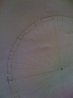
Still working on the pics and drawings...
I guess the best way to describe the build is that it is a motor for a TRON Light Cycle-like hubless wheel.
The one built on a Discovery Channel show by two brothers was still gear-based, rather than a large outrunner.

I guess the basic question is, could a motor of the aforementioned general dimensions (or perhaps even 2 up to 4 of them) power an EV or bike so that it can safely and reliably keep pace with daily highway traffic? By my estimation (largely due to its size) it should.

But to make sure I'm requesting guesstimates from the gentlemen here: What would be the max torque/speed figures based on the motor's dimensions, given that voltage and amps and anything else external to the motor can be changed to your specific recommendations?

Any estimates ( plus caveats, suggestions and comments) would be very much appreciated.

Several experts on ES mentioned that controllers have limitations when the motors are this large (and thus they prefer InRunners). Is that a real show stopper or are there alternatives? Which controllers would be suitable for this application? It would be too expensive to have a controller custom-built for sure.

I'm just scaling up an "ordinary" outrunner to about 15" dia and 3" width and making it into a ring.

Thank you for all your responses! Will endeavor to get pics, drawings and video in time.

Best regards,
BigOutrunner
 
Go to the kjmagnetics site. Look up your magnets. Go to the magnetic field calculator. Take the two magnets with horseshoe configuration. Get the magnetic field strength. From this calculate your magnetic flux. With the estimated electrical motor speed you calculate the derivative towards time to get flux change per second. With the amount of windings you have you can calculate the voltage your motor generates / needs. Calculator the resistance of your windings, estimate the power you can dissipate in them, this gives you the amount of current you can push. Current and voltage give you the amount of power your motor can deliver. Together with the (known) motor speed you can calculate torque.

A child can do the laundry, as they say in Holland :mrgreen:
 
I would bet with that dimension you can get about 600Nm of torque, or 120kW at 2000 RPM for short periods.

It would have no problem driving an EV.

If you want to see what a big outrunner can do, look at protean http://www.proteanelectric.com/

-ryan
 
Biff said:
I would bet with that dimension you can get about 600Nm of torque, or 120kW at 2000 RPM for short periods.

It would have no problem driving an EV.

If you want to see what a big outrunner can do, look at protean http://www.proteanelectric.com/

-ryan

Thank you Ryan! That's the sort of quick estimate - and positive feedback :) that I was looking for.

The problem Protean has is that the drive electronics is also on the hub.
Which makes it heavier than it needs to be. Protean needed to hire Lotus to try to dispel the vehicle dynamics issues. Didn't work.

I'm employing the KISS principle - just a really big outrunner, nothing fancy, except for trying to do everything to keep it light while retaining power.

I am certainly impressed with Bertie's ability to control his Turnigy's with his addition of internal Hall sensors. Algorithm control isn't as good as sensor-based it seems.

All suggestions for max efficiency are certainly welcome.

Thank you again Ryan and all of you on ES!
 
Lebowski said:
Go to the kjmagnetics site. Look up your magnets. Go to the magnetic field calculator. Take the two magnets with horseshoe configuration. Get the magnetic field strength. From this calculate your magnetic flux. With the estimated electrical motor speed you calculate the derivative towards time to get flux change per second. With the amount of windings you have you can calculate the voltage your motor generates / needs. Calculator the resistance of your windings, estimate the power you can dissipate in them, this gives you the amount of current you can push. Current and voltage give you the amount of power your motor can deliver. Together with the (known) motor speed you can calculate torque.

A child can do the laundry, as they say in Holland :mrgreen:

Thank you Lebowski! I will certainly recompute based on your guidelines.
Terrific work on the controller and all the other builds you've shared. Simply amazing!

I'm not certain if it was you who mentioned that you (on your acrylic core build thread) could use SiFe wires cut to short lengths as the center of the core instead of laminations. Perhaps if the top and bottom ends were all somehow terminated over/connected to metal surfaces it would be more efficient/and hopefully lighter than using regular laminations?

Right now I am wondering what effect a acrylic container containing ferrofluid would have on the flux strength if used as the core. Would it just seize, or would the nanoparticles align to produce better results than that of high-purity SiFe? My apologies for all of the childish questions - I'm a still a newbie.

Getting the best power to weight for a motor this size is tricky. Too much of one will offset the other.

My sincere thanks! More suggestions and comments please! Best regards.
 
When did KISS and hubless wheel become okay to combine in the same description, because I want one too? Can we add practical to the equation? :mrgreen:

Since the stator is only going to be a small portion of the circumference I think you'll need a higher pole count for smooth operation. That power estimate may be for a 360° stator too. What's the plan to keep magnetic bits of debris off of the large exposed magnetic ring?
 
h0tr0d said:
Big Outrunner:

Can we have some pics, drawings, etc? Much easier to help that way...

Power and rpm goals?

Volts, amps...?

Hello Gentlemen,

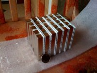
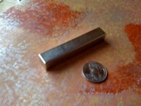
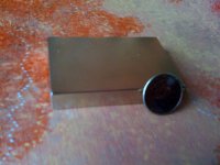
My magnets arrived. Feels like Christmas!

Bonus points to the one who first guesses what I'm up to with the magnets.

Anyway, I'd like to start a firestorm here, by asking this question:

To get the best balance of power and performance from the stator, should I go for Litz wiring or plain round copper?

I want the stator's thickness to be around 3/4" and not more than 1" - the 'thinner' the better, since I want to create a ring and not a donut.

I could test bundling and gluing SiFe wires together for the core rather than go for the usual laminations. Would this help with efficiency or lightness? Suggestions please!

This is going to be one hell of an EV! And there may be three more of these after this is completed.

Again, it is just a 'big outrunner', nothing more. Looking forward to your response!

Thank you All!
 

Attachments

  • photo (3).jpg
    photo (3).jpg
    79.5 KB · Views: 1,480
  • photo (4).jpg
    photo (4).jpg
    33.7 KB · Views: 1,480
  • photo (5).jpg
    photo (5).jpg
    65.9 KB · Views: 1,480
  • photo (6).jpg
    photo (6).jpg
    60.1 KB · Views: 1,480
BigOutrunner said:
To get the best balance of power and performance from the stator, should I go for Litz wiring or plain round copper?
There's not much point in using Litz wire unless you are going to do a coreless design. It will just give you a worse fill-factor....
 
Miles said:
BigOutrunner said:
To get the best balance of power and performance from the stator, should I go for Litz wiring or plain round copper?
There's not much point in using Litz wire unless you are going to do a coreless design. It will just give you a worse fill-factor....

Hello Miles,

No, I'm not going for coreless.
I'm looking at standard laminations if I get no clear suggestions/path here for using SiFe wire bundles or something else.

Looking forward to everyone's input!

The race is ON!

H E L P ! ! !

I need your suggestions to get the very best stator design!

Thanks!
 
John in CR said:
When did KISS and hubless wheel become okay to combine in the same description, because I want one too? Can we add practical to the equation? :mrgreen:

Since the stator is only going to be a small portion of the circumference I think you'll need a higher pole count for smooth operation. That power estimate may be for a 360° stator too. What's the plan to keep magnetic bits of debris off of the large exposed magnetic ring?

Hello John,

Thin section bearings from RBC, Kaydon, NGK and other manufacturers make it relatively easy to go hubless.
However, to keep things really simple for this current task, I will likely used what I've used before - just plain alloys.

I think that compared to the hundreds of components in an internal combustion engine - this big outrunner is far more practical.

So based on feedback I got so far, common round copper is what I should use?

When I look at stators made for solar EVs, they are using Litz and are getting very high percentages of efficiency from their motors - above 95%.
I'm scouring the forum for ideas to improve the stator design - i.e. bundled strands of SiFe wire as core and Litz wiring around it.
Or should I just stick to laminations and common round copper?

Suggestions please!

Thanks!
 
oooh, magnets! :shock: 8)

If I get a vote I'd say keep it simple and try to improve efficiency and performance on the next one.

Once the first one is running I'm sure you'll get ideas for improvements. :)
 
Oh, regarding the magnets it's quite obviously for an attempt at a Halbach array. That won't stop magnetic debris from getting to your exposed magnet ring.
 
John in CR said:
Oh, regarding the magnets it's quite obviously for an attempt at a Halbach array. That won't stop magnetic debris from getting to your exposed magnet ring.


Give the man a beer! :p There are ways to design this to overcome the magnetic debris issue.

But...

I really need help with the stator design gents! Any suggestions to maximize efficiency/power would be very much appreciated.

Here's an idea I picked up from Lebowski's triple stator axial flux thread. I think it still is a very valuable idea and doable. A bit of epoxy between the coated wires, shaping the bunch on a vise or two simultaneously - would perhaps reduce eddy current losses significantly. The method used to bind may perhaps serve as the attachment point.

Lebowski was looking to "wind a coil-core out of coated iron wire" for his application, which is rather too advanced for me. Regardless I would just like to find out if these bunched wires would be better to use than standard laminations.

Here's the thread I'm referring to below:

___________________________________________________

Re: Building a triple stator axial flux motor

by Lebowski
Thu Feb 21, 2013 1:42 am

Forum: Motor Technology
Topic: Building a triple stator axial flux motor

I've thought about using an iron core. Keeping in the spirit of using ordinary and easely available materials, I would wind
a coil-core out of coated iron wire. Here they sell plastic coated 1mm thick iron wire for use in the garden (tying bean stalks
etc). When wound this would give an iron core with (very) little eddy current losses.
Reasons why I haven't done this, I think
it would make the motor impossible to assemble. The coil plate would bend a bit and the iron core would either attach
to the left or right magnet plate, it would be impossible to position the plate in the middle and not have it stick to either
magnet plate. Plus the forces on the magnet plates during assembly would be very difficult to handle.
 
Back
Top