Futterama's power stage for Lebowski's controller IC

Futterama

1 kW
Joined
Sep 1, 2013
Messages
444
Location
Denmark, Scandinavia, Northern Europe
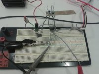
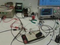
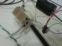
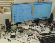
So, I got my Rigol DS1104Z scope (4ch, 100MHz, 1GSa/s) recently, and made room for it on my desktop. So now I'll really start building my RC controller using Lebowski's controller IC.

My aim is to build a RC controller for a SkyRC Beast X528 RC car motor. The motor and controller is going to be used in my 4WD 1:5 scale RC race car. This is not an EV build :wink:

The motor: http://www.skyrc.com/index.php?route=product/product&path=39_48&product_id=141

The controller specs:
- Input voltage: 10S LiPo, 37V nominal, 42V max.
- Current capability: 200A "continuous" current or just a few seconds peak, but enough to run the motor on a track.
- FETs: TO-220 type, 75V or above. Not sure which manufacturer or model yet, but I have a few in mind.
- Bootstrapping FET drivers from TI for testing the first prototype.
- Isolated gate drivers with miller clamp and desat detection for the final version.
- Lebowski controller IC, TQFP SMD type.
- Lebowski style "low inductance output stage".
- Cooling: Modified CPU cooler heatsink and fan.
- Opto input from the RC receiver, no BEC, the receiver and servos will run from a seperate 7.4V LiPo battery.
- Gadget feature ideas (I just love those): WiFi connection to smartphone with various readings (ESC/motor temperature, battery voltage/current, maybe even a battery gauge, max motor RPM) through a webpage using WebSocket for instant data exchange. I'm also planning full access to the Lebowski chip menu from smartphone.

The above features has been updated to reflect my design changes along the way.
 
I'm still leaning to use my new scope so I started out with some gate-source and drain-source readings on a quick 1 FET setup.

It has been some time since I made a gate driver PCB using the Fairchild FAN7190 gate driver so I used this along with a small PIC to generate a low side pulse around 1µs into a ISL9N302AP3 FET (datasheet attached).

The PIC is powered by 4xNiMH cells = 5.12V.
The gate driver is powered by a 3S LiPo battery through a homemade ~8A fuse.
The FET bus is powered by my lab supply (20A current limit).

The setup is a pretty mix of alligator clip wires, SMD PCB and breadboarding :D

I used a coil of copperwire as load.

In the G-S picture, I can see the miller plateau on the rising edge, sweet. In the end of the falling edge, I get this short wavy voltage, this is called ringing, right? What is causing this? The gate loop area is pretty large in this setup. I can see a change if I just get the two wires from the gate driver board closer together, so I guess this is caused by gate loop. Great to see the effect of a tighter gate drive loop area.
 

Attachments

  • 20140216_122240.jpg
    20140216_122240.jpg
    275.3 KB · Views: 4,889
  • G-S_big_gate_loop.png
    G-S_big_gate_loop.png
    14.5 KB · Views: 4,889
  • G-S_small_gate_loop.png
    G-S_small_gate_loop.png
    14.1 KB · Views: 4,889
  • ISL9N302AP3.pdf
    122.5 KB · Views: 138
The schematic for the test circuit is attached.

The D-S measurement looks interesting. I don't quite know what is going on. The scope will see the bus voltage when the FET is off. When the FET turns on, the voltage is at GND level as long as the FET is on. When the FET turns off the interesting happens. The voltage rises to the bus voltage and beyond. I know this is the breaking down of the coils magnetic field that is causing this. But the flat plateau I'm not so sure about. I think it is the lab supply that clamps this voltage. It does not go beyond 36V. The lab supply is rated to 30V. If I lower the bus voltage to 10V, the voltage does not swing to 36V and is not clipped.

So, when the bus voltage is 10V, the voltage will swing to ~32V. These voltage swings, are they caused by the coil inductance? I don't remember seeing this kind of scope picture in the other threads about controller building.

The current through the coil at 10V is 1.8A.
 

Attachments

  • D-S_voltage_swings_above_30V.png
    D-S_voltage_swings_above_30V.png
    16.9 KB · Views: 4,854
  • D-S_voltage_clipped_at_36V.png
    D-S_voltage_clipped_at_36V.png
    14.6 KB · Views: 4,854
  • test_circuit.png
    test_circuit.png
    2.5 KB · Views: 4,854
I wanted to eliminate the lab supply as a source of interference, so I used a 3S LiPo battery for the bus voltage. I also replaced the coil with a piece of resistive wire (around 1m, 3.6A current) and I get the following result. I even used the high frequency probe spring to see if the hook tip or ground alligator clip would interfere.

So what is causing that voltage swing? How to avoid it? The FET is only rated at 30V drain to source, so the voltage swing is not good for the FET. I really want to understand these things.
 

Attachments

  • D-S_battery_and_resistive_wire.png
    D-S_battery_and_resistive_wire.png
    14.9 KB · Views: 4,852
When there's no path for the coil current to continue to circulate when the low FET is turned off the like in your test circuit, the coil will raise it's voltage until the current continues to circulate, which means it will raise it until something "breaks down"; in your case, it's probably the FET breaking down and entering avalanche. When you "press" the D-S voltage of a FET beyond it's limits, it will act like a zener diode clamping the voltage to a certain value a it above the rated limit; that's probably where your "cliping" to 36V is coming from. This means current is flowing through the FET, and it's probably getting hot. That's an "invalid" test, you need to add a free-wheeling diode or some other way to let the coil "discharge" (given the motor control context).

p.s. by the way, with a 4 chn scope I would be making use of all channels to gain higher insight into the stuff, otherwise I would have saved money by acquiring a 2 channel scope instead :)
 
Njay, thanks for posting 8)

Oh, so the 36V is caused by the FET. Interesting.

Yeah, I got myself a 4ch scope to avoid a similar problem I was in 3 months ago when I got myself a 2ch 12MHz PC scope, the bandwidth was way too low for this kind of stuff. I'm just getting to know the scope, so my hands are full with 2 channels already :lol:

I built a quick Lebowski style low inductance output stage with two busbar plates with 2 FETs attached next to a ELMA RJB 25V 1000µF aluminium cap (the best I got right now) and a WIMA metallized polyester cap. The results are much better, especially at low current.

Shouldn't the high side FETs body diode act as a freewheel diode in this setup? (yeah, I forgot to ground the gate of the high side FET...)
 

Attachments

  • low_inductance_low_current.png
    low_inductance_low_current.png
    11.4 KB · Views: 4,852
  • low_inductance_high_current.png
    low_inductance_high_current.png
    15.9 KB · Views: 4,852
To have a realistic representation the gate of the high FET should be connected to its source, not to ground.
The FET's diode will act as the freewheel diode, like you said.

There's some ringing in the gate circuit (blue trace) when you switch off, did you twist the gate-drive wiring ?
 
You should connect T3's gate to source and not leave it unconnected.

The huge ringing on the yellow trace can also be caused by too much inductance between the low FET's drain and the exit point to the load.
 
Lebowski said:
...the gate of the high FET should be connected to its source, not to ground.
Yes, of course, doh, mind fart Futterama :shock:

Lebowski said:
There's some ringing in the gate circuit (blue trace) when you switch off, did you twist the gate-drive wiring ?
Yes, it is very well twisted, about 15-20cm long. I can post a few pictures later today along with the gate driver PCB layout.
Now that I think about it, for some reason I installed a 0R low side gate resistor on that gate driver PCB when I soldered it. It should be at least 2R7 when driving the FET using a 4.5A gate driver at 12V. I will change the 0R resistor to a higher value and try again.
 
True, a certain amount of resistance at turn-off is necessary, both to limit the current (protect driver IC) but also to dampen any ringing (as the wiring (L) and gate capacitance make an oscillating LC combination that needs to be dampened (with an R))
 
Without having the components on a PCB it's going to be hard to control gate loop area.
Add a some snubber caps (not RC snubber type, just caps) to the rail probably 0.47-1uF polypropylene dielectric as close to the two FETs as possible along with some 1 large cap low ESR electrolytic like a 470uF, You'll probably need to go eletrolytic for the rail unless you have a decent size 10-20uF polypropylene cap laying around. These should be as close to the FETs as possible and have very short leads. Do not build your controller like a typical RC controller, they are full of design fail, especially when they use long leads on the electrolytic caps by bending them 90 degrees and having them be almost 1cm long.

You switching time looks like its super fast, you can up your gate resistor to a much higher level or add a G-S capacitor of 10-50nF. I found that a 20ohm gate resistor would let me switch < 150nS which is too fast, but adding 62nF of G-S capacitance (which is a lot) slowed my switching down to about 350nS when testing with single pulses into coils on the bench. Now that the same setup is in my working Lebowski controller I see switch times of about 275nS. The slower you start out, the easier it is to get problems under control, then start tweaking for faster speed.

With most SMD components, they just can't shed the heat, you will NOT be able to get 200A continuous with them (mabye if you controller is the size of a sheet of notebook paper), especially if you mean 200A RMS ;) Why do RC controllers always use SMD MOSFETs? They make sense for small low current applications or very short burst high current, but a single TO-247 FET will handle more current than 6 parallel typical RC controller SMD MOSFETs can, even a TO-220 which uses the same components but has it's tab attached to a decent heat sink will slaughter most SMD MOSFETs on thermal transfer.

Just remember that when it comes to RC, the numbers you see advertised are what the marketing people say they should be at, because bigger = better and many idiots will buy ten 75A controllers for $20 each + shipping every time they blow up, but won't pay $200 for a 25A continuous rated controller that would never blow up and blow the doors off the "75A" controller. The beauty of marketing knowing how to exploit the uninformed.

I have some 200W PC speakers power by a 20V 2A supply... ohms law what?

How much current are you putting through that coil?

BTW, I have been looking for a 4WD 1/5th scale electric setup, which one are you using? I figured it would be a good design platform for testing small controllers out on because I'm kicking around the idea of building a small sized controller targeted towards the huge RC market which can actually do ~50A, maybe even 75A continuous, in RC terms this would be a 500-750A controller.

I hate marketing people!

P.S. nice scope! I have a DS2072 which has been "upgraded" to 200mhz 56Mpt storage. I've been using this scope for 3 weeks and still find new useful features, there are so many in these new scopes.
Just a word of warning if you haven't seen it posted in mine or Arlo1's thread, do not connect probe ground clips to different ground sources. If you connect one ground clip to the low side source and another ground clip to the high side source, you just shorted the high side source to ground through your scope! Evidently they are pretty robust as Arlo1 melted his ground clip and the scope was OK. Just watch out for this trap.
 
Zombiess, thanks for taking your time to post in my thread, I know you are busy with your own controller.

SMD components, well, I have a plan on how to cool them. I have already put, I think it was 50A, through one of the SMD FETs, a 30V 0.99mOhm 100A, and I had no problems cooling it with a small heatsink and thermal paste in between. This was not an inductive load and I don't think I was switching so it could look different when they are in a controller.
I am pretty positive that MGM controllers use SMD devices, how else can they make a 250A controller, that actually lasts with a 200A motor (I have seen a datalog that said 175A) in such a small package?

400x400.jpg


I'm going to try it at least 8)

The current through the coil at 10V is 1.8A.

I'm rebuilding my gasoline car, a Nutech Thunderbolt II Pro Race:
0579076.jpg


Regarding the scope, yeah, I have been wondering whether the ground clips were connected. I did also learn (by sparks) then the lab supply ground potential is the same as for the scope - they are both connected to the household earth connection. That's also why I use batteries, they have no common ground :lol:
It's probably the same for the PC, since my PICkit2 got disconnected when the small sparks flew :roll:
 
Tied the high side gate to high side source.
Moved CH2 (blue traces) ground clip closer to FET. There is not enough room for CH1 ground clip right now.
Moved load alligator clip from high side FET source wire to the FET source leg.
Edit: Changed the 0R SMD gate resistor to a through hole 10R resistor. I remember why I put 0R here, I don't have any low value SMD resistors besides 0R and 75R, so my plan was to add a through hole resistor somewhere in the circuit anyway.

The electrolytic cap is 42mOhm, 1690mA ripple.
The red block is a 0.1µF WIMA metallized polyester, the only type I got right now.
Twisted white/yellow wires are 18cm long.
Load is resistive wire, 10A at 10V.

Scope image is pretty clean, but I'm starting to have a mess on my table :D
 

Attachments

  • 20140217_200819.jpg
    20140217_200819.jpg
    287.9 KB · Views: 4,800
  • 20140217_200837.jpg
    20140217_200837.jpg
    223.8 KB · Views: 4,800
  • 20140217_200844.jpg
    20140217_200844.jpg
    185.8 KB · Views: 4,800
  • D-S_G-S_battery_and_resistive_wire2.png
    D-S_G-S_battery_and_resistive_wire2.png
    14.9 KB · Views: 4,800
Futterama said:
Regarding the scope, yeah, I have been wondering whether the ground clips were connected. I did also learn (by sparks) then the lab supply ground potential is the same as for the scope - they are both connected to the household earth connection. That's also why I use batteries, they have no common ground :lol:
It's probably the same for the PC, since my PICkit2 got disconnected when the small sparks flew :roll:

Don't worry too much if no harm was done and chalk it up to a good learning experience. We have ALL done it.

I've lost count of accidental shorts when testing and finally learned to insulate my temporary connections, including ones with alligator clips with masking tape, because when it falls apart after getting bumped, moved there is some unnatural force at play that WILL cause a conductive path resulting in sparks no matter how creative you though you were.

As for that controller, 175A or 200A for how long, continuous means always on. I bet that controller would die in under < 10 seconds at it's 250A rating. A 200A motor is only a 200A motor when it's drawing 200A, most of the time it's probably a 30A motor ;) A 200A continuous motor would drain a 5AH pack in <1.5 mins. Just for reference, I have a 26lb/11.8Kg out runner I pump 175A peak into and after 15 or so 5-10 sec bursts of 100-175A it gets warm.

You have to read between the B.S. marketing that is put out and look at it from an electrical / physics stand point. It might do 200A, but that is probably doesn't last for more than a few seconds peak.
 
Futterama said:
Tied the high side gate to high side source.
Moved CH2 (blue traces) ground clip closer to FET. There is not enough room for CH1 ground clip right now.
Moved load alligator clip from high side FET source wire to the FET source leg.

The electrolytic cap is 42mOhm, 1690mA ripple.
The red block is a 0.1µF WIMA metallized polyester, the only type I got right now.
Twisted white/yellow wires are 18cm long.
Load is resistive wire, 10A at 10V.

Scope image is pretty clean, but I'm starting to have a mess on my table :D

Looks better, but you really need an inductive load to show you major issues. With a purely resistive load the scope shots should be relatively clean but on the bread board you are going to have stray inductance all over. You'll probably find you get much better results testing on a PCB with tighter tolerances.

*edit*

I just noticed you built your gate driver on a PCB. You should try making a new one with a ground plane and compare it. Gate driver circuit layout is incredibly tricky, but it looks so simple in the schematics because there are so few parts. I literally spent 1 MONTH (maybe it was 2, I do remember many late nights of my wife telling me it's time to go to bed, then staying up 2 more hours re arranging components on the board layout in KiCad) getting my gate drive layout to get a passing score from HighHopes and that was with him coaching me. He has higher standards than most and getting close to his standard was my goal.

BTW, you call that messy, this is my work bench from a few minutes ago which oddly enough looks pretty organized in the picture. Controller has 6 FETs in it with tiny heat sinks right now for bench testing. It might be able to do 10A from the power supply without a fan and be OK in this state "might".
Work Bench.jpg
 
Zombiess, you are completely right about motors and controllers. The motor I'm going to drive is rated at 192A peak. My 15kg RC car will probably not be able to create the kind of mechanical resistance it takes to reach motor peak, at least not for long. When driving on a track, it is (full) throttle a few seconds at a time, then brake, coast around the turn, throttle again, brake, coast and so on. If I choose to go to the beach with the car, the motor might see some kind of peak when opening full throttle, but again, only for a few seconds before the car/motor hits top speed. We have to remember, I'm building a RC controller, which, compared to an ebike controller, is low voltage, short time load. No long steep hills with 90kg human on board. With this in mind, I'm not afraid of using SMD FETs. And you are probably right about the MGM controller too, if it was loaded with 250A for an extended period of time, it might not hold up. But we can't really know that unless someone did the test. MGM is not chinese so I think they did their homework on this.

Regarding inductive load, the coil I found does not draw more than 1.8A at 10V, so I'll have to find something else that will draw more current. I think I will try to wind the copper wire around an iron core, and do some calculations on it so I can have an idea of the coil inductance and peak current. Well, peak current can be measured by just connecting it to the lab supply for long enough to read it's current draw (only depends on the coil wire resistance, right?).
And I know the breadboard is not optimal, but I have to start somewhere. When I know more, I will design a more complete PCB, adding things step by step.

Ground plane. Well, I have never fully understood this. The ground plane is not just a plane that is connected to GND somewhere, right? For the ground plane to do it's work, the return current has to flow here, correct? Current return path through ground plane, does that sound about right? It's kinda like when Lebowski is twisting his gate-source wires, to reduce the inductance, the current flows to the gate through one wire and returns in the other, and the inductance is cancelled due to the opposing flow of current. Same with ground plane, current flows through a top PCB trace and should return on a nearby ground plane, to cancel the inductance. Gibberish or did I actually understand the appnote I once read on ground planes? :lol:

Nice work bench, you have to keep it tidy, I have more room on my table (90cm deep, 275cm wide) where I can put my mess, it can start to pile up :roll:
Picture is from before I mounted the monitors to the wall to allow room for my scope.
 

Attachments

  • pileup.jpg
    pileup.jpg
    261.5 KB · Views: 4,764
New air core coil made from 100 turns 0.75mm magnet wire. Coil dimensions are 43mm diameter, 85mm long. Calculates to 174µH. Draws around 22A at 20V according to my lab supply (current limit is somewhere just above 20A but at 20V I didn't hit the limit/overload).

View attachment 3
I added the last two scope channels and found a problem with my PIC output pin, it had trouble pulling to ground, so I just picked another pin on the PIC12F1840. I also changed the way I fire the pulse. Room is getting tight with all those probes :D

20140218_213558.jpg
Blue trace is bus voltage at the alligator clips coming from the lab supply.
Yellow trace is FET drain-source at the FET pins.
Cyan trace is FET gate-source at the FET pins.
Pink trace is PIC output.
Notice fall time on the yellow trace is 60/64ns. Is this what you call the FET switching time? Or are we talking about the gate rise time when talking switching time?
It's fun to see the miller effect, the gate voltage is not rising until the FET drain voltage stops falling.

4ch_new_coil1.png
Bus voltage fluctuations just below 2V.

4ch_new_coil2.png

I had the lab supply disconnected at one point and I still got a good reading. The bus voltage is dropping unnoticeable when it's only the capacitors supplying the short current pulse to the coil.
The bus voltage fluctuations were exactly the same with the lab supply disconnected. Is it correct to assume that better caps would make the bus voltage more stable when the FET turns on?
 
Some of that noise is not going to be circuit noise, but instead common mode noise. I measured this on my scope at different levels by attaching the ground clip to the probe tip to the high side FET source. Anything that shows up as noise is being picked up by the probe/coax/scope and is not part of your true signal. I have some differential probes and a 500mhz active probe now, just haven't had the chance to see how much difference they make in rejecting noise like this. It's always good to check how much noise your scope has.

This video will show you just how sensitive your scope is to noise. Try it out with your scope, it's pretty informative and something you need to be aware of when measuring.

[youtube]sUG_sjS67K4[/youtube]
 
Those bus voltage fluctuations are caused by the top mosfet's diode reverse recovery current when the bottom fet turns ON. Low ESL cap on V+ to V- by the FETs, minimal layout inductance and slower bottom FET turn ON are the ways I know of to keep that under control.

Your FET seems to be switching off very very very slowly...
 
Cool good to see another controller build.
 
Since I'm asking a lot of questions in my post, I might be hard for you to keep track of, so here is the list of questions until now:

1. The wavy voltage is called ringing?
Self-answered: Yes, no one seems to have commented on incorrect terms so I must have got it right :wink:

2. What is causing the ringing at the gate when switching off?
Self-answered: Poor layout (breadboard) and 0R gate resistor.

3. What is causing the drain-source voltage swings and ringing at turn off?
Answered: Missing high side FET (freewheel diode) and too high bus voltage for the 30V rated FETs (going avalanche at 36V).

4. Shouldn't the high side FETs body diode act as a freewheel diode?
Answered: Yes, but remember to tie the high side FET gate to it's source when not in use.

5. Can I measure max coil current by leaving it connected to my lab supply until the voltage is stable? I mean, the coil is acting as a resistor when the voltage is constant from what I know.
Unconfirmed, but I'm pretty sure I got it right.

6. Questions about ground plane:
a. The ground plane is not just a plane that is connected to GND somewhere, right?
b. For the ground plane to do it's work, the return current has to flow here, correct?
c. Current return path through ground plane, does that sound about right?
It's kinda like when Lebowski is twisting his gate-source wires, to reduce the inductance, the current flows to the gate through one wire and returns in the other, and the inductance is cancelled due to the opposing flow of current. Same with ground plane, current flows through a top PCB trace and should return on a nearby ground plane, to cancel the inductance.
d. Gibberish or did I actually understand the appnote I once read on ground planes?
Unanswered.

7. Notice fall time on the yellow trace is 60/64ns. Is this what you call the FET switching time? Or are we talking about the gate rise time when talking switching time?
Unanswered.

8. Is it correct to assume that better caps would make the bus voltage more stable when the FET turns on?
Answered: Low ESL cap on V+ to V- by the FETs, minimal layout inductance and slower bottom FET turn ON.
 
Regarding slow FET turn off, I did a quick test. I replaced the coil with a piece of resistive wire with roughly the same current draw but with much lower inductance. The turn off time is longer with an inductive load, why is that?

Also the bus voltage is dropping noticeably with the resistive wire and there is some ringing when the FET turns off, that is not there with the inductive load. What is going on here? I would have thought it should be the other way around.

Coil load:

coil_load.png

Resistive wire load:

resistive_load.png

The used FET switching characteristics:

 
I received some TI UCC27211/UCC27211A gate drivers today (I haven't figured out the big difference between the "A" version and non-"A" version yet). They are "only" rated 4A compared to the fairchild 4.5A. But they have like 10% of the propagation delay so they are/should be much faster. And they have an internal bootstrap diode, yeah, less board space :D

So until I finish a test PCB for the new drivers, I wanted to do some more measurements on my circuit. It takes almost 1.3µs from the PIC has lowered it's output, to the MOSFET is fully off. This seems like a long time.

I put a probe on the gate driver supply on the PCB to see if there was any drop in the 12V supply when firing the pulse, but it was rock stable.

I then disconnected all my scope probes and put one across the gate resistor. I disconnected the lab supply before firing the pulse (the scope and lab supply shares ground potential) and got these shots.
I'm not quite sure what to think about it. The purpose was to somehow find the gate current and since U/R = I and I know R=10R, I needed to find the real U. Why it is not 12V as the gate driver supply voltage, I can't figure out, but 6.8V and 8.2V over a 10R resistor is only 680mA and 820mA. I should really try a 2.7R gate resistor. I'll be back 8)
 

Attachments

  • gate_resistor_charge.png
    gate_resistor_charge.png
    13.5 KB · Views: 4,681
Back
Top