Adding turns to a cyclone motor

Joined
Jul 20, 2013
Messages
339
Location
Sydney
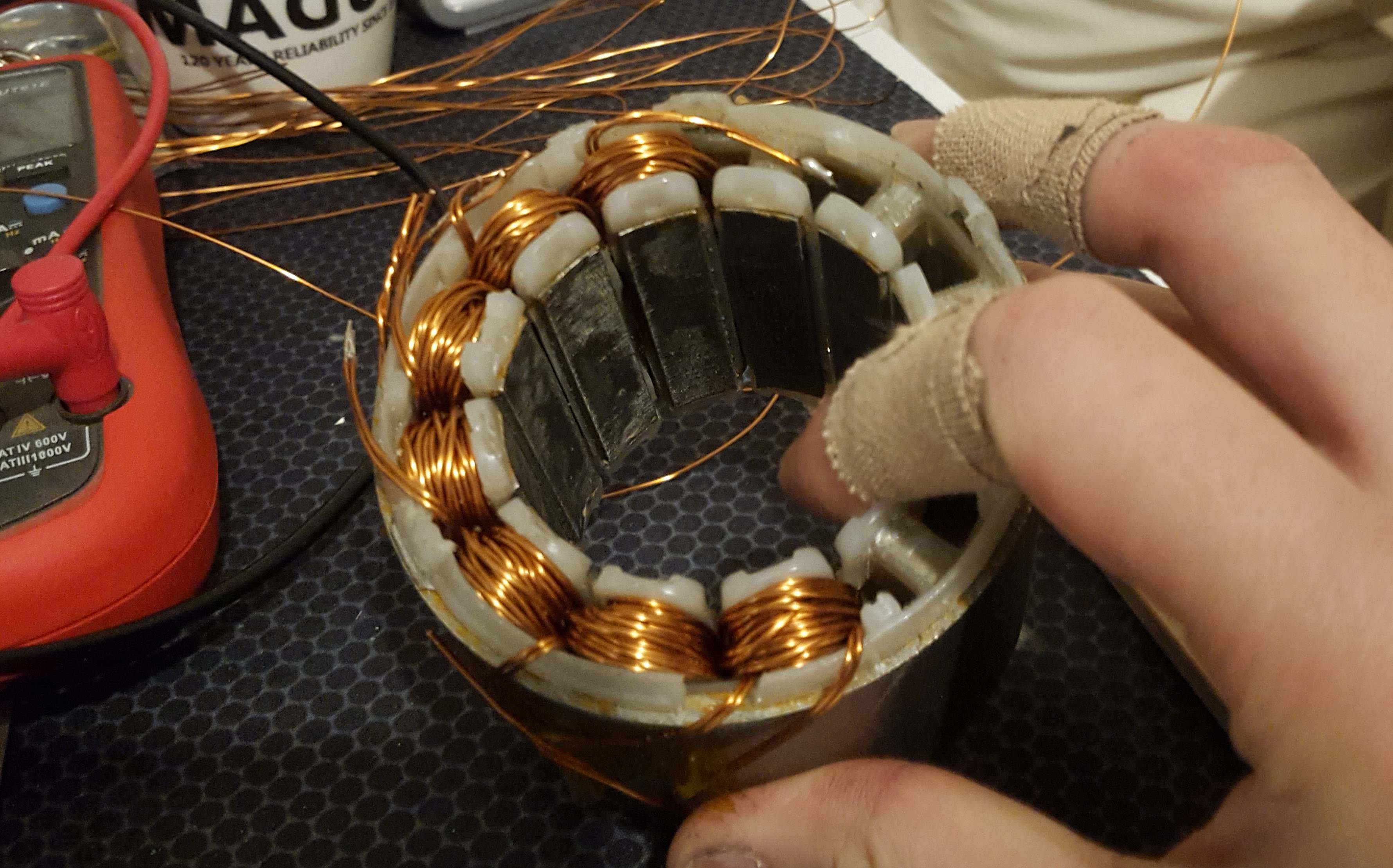
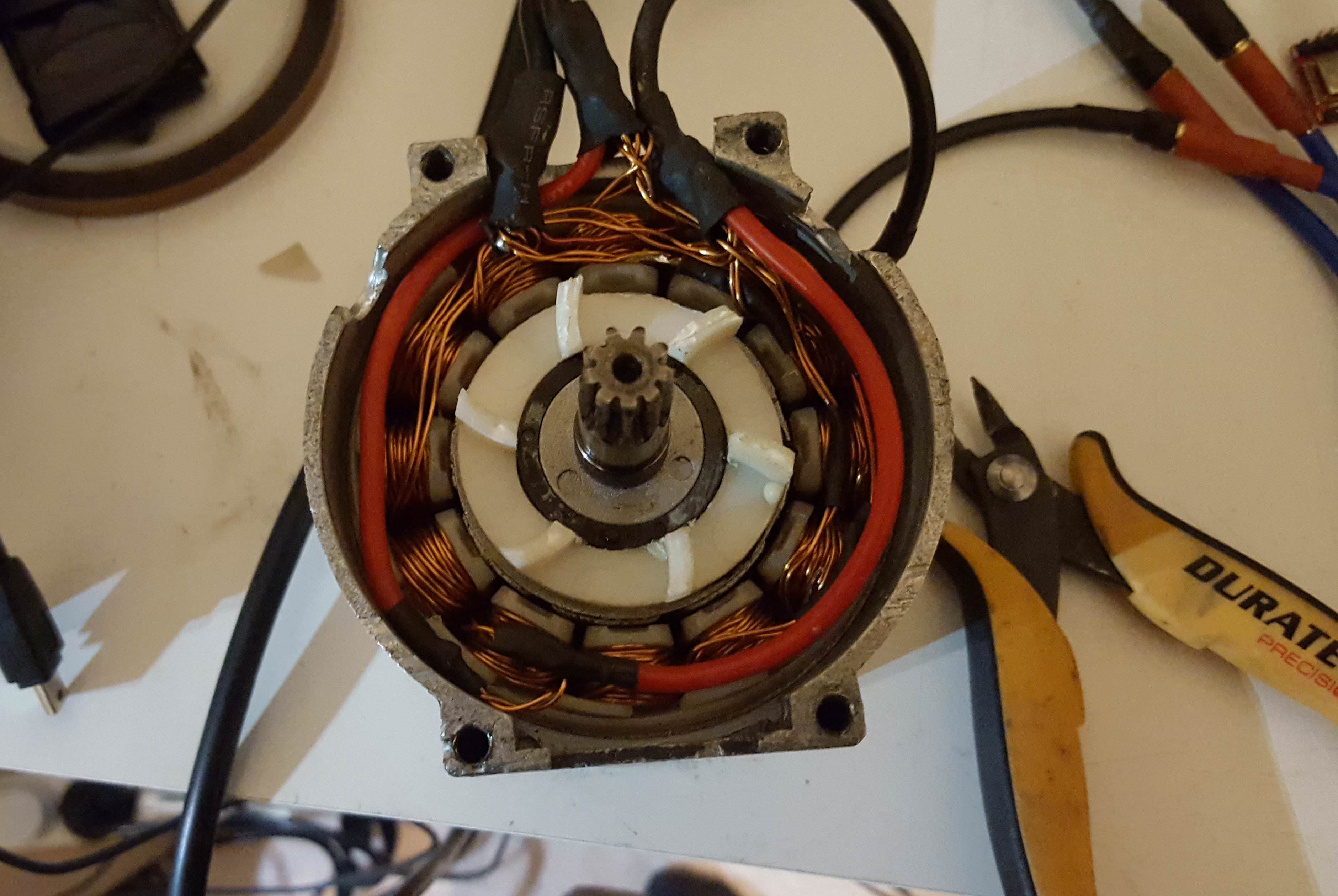
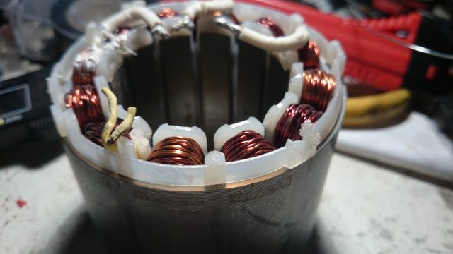
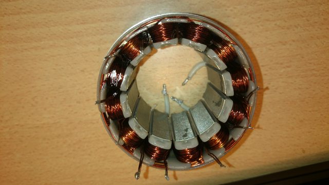
I've recently removed the stator from a cyclone inrunner motor. As you can see from the pics, the copper fill isn't exactly great. Is there any reason why I could not separate the windings from the star termination and throw a few extra turns on each stator tooth? It seems like there is quite a bit of unused space between the teeth. There should also be plenty of room on the ends of the stator teeth since some space will be freed up by removing the hall boards and running sensorless. Hopefully this should decrease the kv a little and increase the output of the motor a bit.

oyfRtuWl.jpg


sQo1KrAl.jpg
 
First: it's not going to be as easy as it might seem to add to the windings: wire is a lot harder than you'd think to get wrapped around in there. ;)

If you add turns you change it's Kv, which means it won't spin the same speed for the same voltage.

If you want to add copper fill without doing that, you'd have to unwind the wire and parallel multiple sets of windings around the tooth, that equal the same number of turns it had before. Essentially making the wire "thicker" by doubling up the windings.

It doesn't look like there's enough room to do that double winding with existing thickness of wire, so you'd have to go with smaller gauge wire, which means you aren't going to gain as much as you might expect out of it when done.

If you're wanting to add more current capability to it, without changing anything else about it, that's the only way I know of, but there are many threads about winding motors, and how they work, and what affects what else, if you look around this subforum--maybe you can find something else that will help.
 
I just had a play around with the stator and some wire. Single stranded wire equivalent to the two parallel strands seems like it would be hard on the fingers. Two parallel strands of similar diameter to the original did seem much easier to wind with and fill the gaps. There definitely seems like there is room for more. It looks nothing like the overflowing windings on hub motors and most brushless DC motors I've played with. Though I highly doubt I could achieve that level of copper fill.

This seems very much like a turd polishing exercise :)
 
I would rewind other motor only, if it is fryed and really worth the hastle. At least have fun and produce some plasma with it first. :evil:
P.S. Have a set of new fets for the controller for after plasma event.
 
No plasma yet!

I added four turns on to each stator tooth without too much difficulty. Didn't rewind, just added to the existing turns since there was enough space. The kv hasn't dropped as much as I thought, about 10%. There must be more turns on each tooth than I thought.

The no load current has dropped a bit with the kv, so I suppose it can't be much more inefficient than the original config.

Would it be fair to say that I haven't really improved the current handling, only the torque per amp?
 
district9prawn said:
Would it be fair to say that I haven't really improved the current handling, only the torque per amp?
I'd say both. What you've done is increase Kt without the resistance penalty paid when reducing the cross sectional area of the windings. Obviously, the windings are now longer but the resistance increase from this is pretty much in direct proportion to the increase in Kt. As heat generated follows the square of the current, you've increased the current handling relative to torque output but, obviously, not the current handling in absolute terms....
 
If there's one thing I've picked up from recent discussions about motors is that's quantity of copper on the tooth is all that matters in improving efficiency and power-handling. How it's wound (length Vs. cross-sectional area) makes little difference.
 
How did you get the coils out of the housing ? they are stuck in their very tight from my experience ???

Also wire thickness and type did you use ?

Will adding these 4 turns increase the peak motor efficiency ? or Just move it down to a lower RPM due to the lower KV ?
 
jk1 said:
How did you get the coils out of the housing ? they are stuck in their very tight from my experience ???

Also wire thickness and type did you use ?

Will adding these 4 turns increase the peak motor efficiency ? or Just move it down to a lower RPM due to the lower KV ?

Getting the stator out is pretty brutal. I make a trumpet shape out of polymorph that sits on the rim of the motor housing and bash the motor like a caveman until the stator is free :D

I doubt there is an improvement to peak efficiency. But there should be a bit more torque across the whole efficiency range compared to before.
 
How did you go with this change with 4 extra windeings ? did you get the motor back together and take it for a ride ? does it feel any different ? i,e does it feel like it has more torque for the same RPM ? Also is your peddle cadence noticably lower if your Kv reduced by 10% ?
 
jk1 said:
How did you go with this change with 4 extra windeings ? did you get the motor back together and take it for a ride ? does it feel any different ? i,e does it feel like it has more torque for the same RPM ? Also is your peddle cadence noticably lower if your Kv reduced by 10% ?

It doesn't really feel any more powerful at any given moment. If my pedalling cadence is a bit on the slow side for a decent period of time I reckon there is an improvement in efficiency. Can't tell what difference it makes in temperature as I drilled holes in the casing, ditched the halls and used the space for a small fan instead so it never overheats anyway.
 
How did this test with 4 extra winding turn out ?

How many turns is their on the original setup, that 4 more adds only 10% reduction in KV ? This would move the torque curve down to a lower RPM which is a good thing to reduce peddle cadence, did you notice this benefit ?

Also do you have any photos on how you did it ? did you remove the circuit board from the back side and add them on that side or do you add the turns on the front side ?
 
district9prawn said:
No plasma yet!

I added four turns on to each stator tooth without too much difficulty. Didn't rewind, just added to the existing turns since there was enough space. The kv hasn't dropped as much as I thought, about 10%. There must be more turns on each tooth than I thought.

The no load current has dropped a bit with the kv, so I suppose it can't be much more inefficient than the original config.

Would it be fair to say that I haven't really improved the current handling, only the torque per amp?

I have simulated the influence of the fill factor at the 350W Cyclone motor with gearbox. An improvement with a factor 2 (which is impossible) increase the efficiency just about 2,5%, so for instance from 86% to 88,5%. So this doesn’t make much sense. But the copper loss decreases with 1 / fillfactor.
I prefer a motor of 36V instead of 24V which requires rewinding; Cyclone doesn’t sell 36V motors at 350W. Can you add pictures that show the fill factor more in detail? Is the rewinding hard to do?
 
Reading through the forum I have seen different numbers appear for the kV of the 650-1200W cyclone motor. Some reports are 150 while other are more like 125, is there a consensus on this?
Also I am a newbie here (first post) if a 4 turns increase gave 10% reduction in KV does that mean anything for calculating new KV, is there an inverse relationship? ie. you have a 10% decrease in KV therefore you've increased the turns by 10% --> The turns you added were 4 so therefore there were 40 to begin with?
Cheers
 
how did you remove the stator? they are pressed in and there is no way to get tools to pull it out

update:

shortly after i wrote this i figured out you can get the stator out by using a torch to heat the case and then using a gas duster ( r134a or r152a refrigerant) and spray the liquid into the core to shrink it microscopically and cause the case to come off easier.
 
I know this is an old post but it is a top match on google when searching rewinding cyclone motor

there is 28 turns of 2 parallel 22awg wires ( 19awg equivalent)
you can fit more than 34 turns of 19awg in the motor with the standard plastics or you can shave back the plastic and do 28 turns of 18awg but its not easy ( 33% more copper fill !)

with 28 turns of 18awg new ceramic bearings in the motor and gearbox i can pull 2kw for 10 mins and its not even crazy hot ( 16s lifepo4 50v 40a max battery 90A max phase current)

i have run it with 70v 40a ( 2800w) for around 5 mins without it getting to hot (no more than 60c)

( this is all done as testing when i am using the bike as transport i have it set to 250w 5a battery 48v with 75A phase current for quick starts easy to stick to 15.5mph gets crazy good range )
 
you can fit more than 34 turns of 19awg in the motor with the standard plastics or you can shave back the plastic and do 28 turns of 18awg but its not easy ( 33% more copper fill !)

with 28 turns of 18awg new ceramic bearings in the motor and gearbox i can pull 2kw for 10 mins and its not even crazy hot ( 16s lifepo4 50v 40a max battery 90A max phase current)

i have run it with 70v 40a ( 2800w) for around 5 mins without it getting to hot (no more than 60c)

Nice work ! how you did the rewind it ?

For the 19AWG did you just add some turns to the existing or did you rewind from scratch ?

For the thicker 18 AWG what is the KV after doing that ? i think normally the motor is 125to 150KV with the standard wiring (28 turns of 2 parallel 22awg wires ( 19awg equivalent)) what is it after changing to 28 Turns
 
jk1 said:
you can fit more than 34 turns of 19awg in the motor with the standard plastics or you can shave back the plastic and do 28 turns of 18awg but its not easy ( 33% more copper fill !)

with 28 turns of 18awg new ceramic bearings in the motor and gearbox i can pull 2kw for 10 mins and its not even crazy hot ( 16s lifepo4 50v 40a max battery 90A max phase current)

i have run it with 70v 40a ( 2800w) for around 5 mins without it getting to hot (no more than 60c)

Nice work ! how you did the rewind it ?

For the 19AWG did you just add some turns to the existing or did you rewind from scratch ?

For the thicker 18 AWG what is the KV after doing that ? i think normally the motor is 125to 150KV with the standard wiring (28 turns of 2 parallel 22awg wires ( 19awg equivalent)) what is it after changing to 28 Turns

I was just crazy striped the motor down ordered some 18 awg wire shaved down the plastics and wound 25 turns on all 12 slots leaving a 1m of wire extra on each end so i could go back around and add 1 turn at a time untill it was full of copper to be honest i could have got 30 or 32 turns if i had spent more time winding it neat as there is still some space

18 awg 28turns is nearly the same kv as the turn count is what effects the kv for every 2.8 turns you add you get 10%slower rpm 19 awg is the same as the 2 parallel 22awg they use so you could just add 3 or 6 or 9 turns depending on how well they wound the motor in the factory
 
I may as well necro my old thread since others have added good information to it.

I recently re wound my motor which somehow burned one phase. Controller problem?
I went for lower kv since I've been using 12s lately but still want 3-4kw peak. This is 24 turns of double 0.71mm.

XjshgT9.jpg


After cutting the blades back on a random pump impeller to fit it doesn't move much air but still makes a big difference since the heat path is so poor. Running sensorless now. I later added/enlarged holes in the housing.

c53hd0t.jpg


As others have reported sustaining 3kw for a few minutes is no problem.

https://imgur.com/4locV3V
https://imgur.com/JZiqcKl
https://imgur.com/WzkOH7r
 
Back
Top