Skalabala
1 kW
Hi members ")
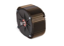
My sensored big block style motor has an erratic miss fire :|
It runs smooth and then miss fires like a car engine
Like, zzzzzzzz t t zzzzzzz t zzzzzzz t t t zzzzzzzzz t zzzzzzzz
My sensored big block style motor has an erratic miss fire :|
It runs smooth and then miss fires like a car engine
Like, zzzzzzzz t t zzzzzzz t zzzzzzz t t t zzzzzzzzz t zzzzzzzz